


tracing wiring fault in 1930s house...mis-wired switch??
HU-288577437
4 years ago

Featured Answer
Sort by:Oldest
Comments (24)

mike_kaiser_gw
4 years agoRelated Professionals
Fort Washington Kitchen & Bathroom Remodelers · Glen Allen Kitchen & Bathroom Remodelers · League City Kitchen & Bathroom Remodelers · Lomita Kitchen & Bathroom Remodelers · Panama City Kitchen & Bathroom Remodelers · Cumberland Painters · Kissimmee Painters · Coos Bay Painters · Martinez Painters · Needham Painters · North Charleston Painters · Worthington Painters · Melville General Contractors · Livingston Handyman · Maple Grove Decks, Patios & Outdoor EnclosuresHU-288577437
4 years agoStax
4 years agolast modified: 4 years agoHU-288577437
4 years agoHU-288577437
4 years agoHU-288577437
4 years agolast modified: 4 years agoHU-288577437
4 years agoHU-288577437
4 years agolast modified: 4 years agoHU-288577437
4 years agoDavidR
4 years agolast modified: 4 years agoHU-288577437
4 years agoRon Natalie
4 years agoHU-288577437
4 years agoHU-288577437
4 years ago- PRO
BobH
4 years ago 
Ron Natalie
4 years agolast modified: 4 years ago
Related Stories

HOMES AROUND THE WORLDWorld of Design: A House That’s Barely There
A rural Australian home blurs the boundaries between indoors and outdoors, camping and permanence, privacy and transparency
Full Story
LIFEThe Polite House: On Dogs at House Parties and Working With Relatives
Emily Post’s great-great-granddaughter gives advice on having dogs at parties and handling a family member’s offer to help with projects
Full Story
LIGHTINGWhat to Know About Switching to LED Lightbulbs
If you’ve been thinking about changing over to LEDs but aren't sure how to do it and which to buy, this story is for you
Full Story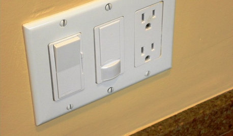
GREAT HOME PROJECTSHow to Install a Dimmer Switch
New project for a new year: Take control of your lighting to set the right mood for entertaining, dining and work
Full Story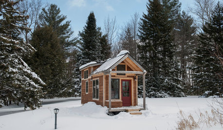
TINY HOUSESHouzz Tour: A Custom-Made Tiny House for Skiing and Hiking
Ethan Waldman quit his job, left his large house and spent $42,000 to build a 200-square-foot home that costs him $100 a month to live in
Full Story
SELLING YOUR HOUSEHow to Style Your Home for an Open House
Our room-by-room overview explains how to make your home more appealing to potential buyers
Full Story
ORGANIZINGOrganizing Secrets: It’s the Little Things
Get these 8 small areas under control for a major boost in overall tidiness at home
Full Story
REMODELING GUIDESGet What You Need From the House You Have
6 ways to rethink your house and get that extra living space you need now
Full Story
HOUSEKEEPING10 Problems Your House May Be Trying to Show You
Ignore some of these signs and you may end up with major issues. We tell you which are normal and which are cause for concern
Full Story
REMODELING GUIDES10 Tips to Maximize Your Whole-House Remodel
Cover all the bases now to ensure many years of satisfaction with your full renovation, second-story addition or bump-out
Full StoryMore Discussions


DavidR