


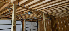
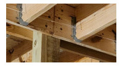
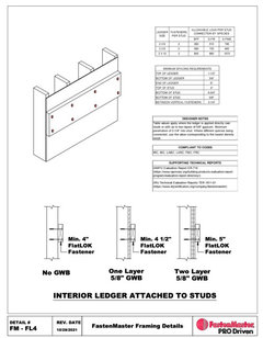
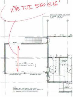
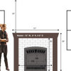
Is this structurally sound?
Craig Foster
last year
last modified: last year
Featured Answer
Comments (38)

Craig Foster
last year PRO
PROMark Bischak, Architect
last yearRelated Professionals
Lafayette Architects & Building Designers · Palos Verdes Estates Architects & Building Designers · Riverside Architects & Building Designers · Pacific Grove Design-Build Firms · Orange City Home Builders · Artesia General Contractors · Havre de Grace General Contractors · Keene General Contractors · Middletown General Contractors · Mount Laurel General Contractors · Murrysville General Contractors · Niles General Contractors · Panama City General Contractors · Parsons General Contractors · Troy General Contractors PRO
PROJoseph Corlett, LLC
last yearlast modified: last year
just_janni
last year
T T
last yearT T
last yearres2architect
last yearlast modified: last year
3onthetree
last year PRO
PROVirgil Carter Fine Art
last year3onthetree
last year
worthy
last yearlast modified: last yearres2architect
last year- PRO
Mark Bischak, Architect
last year - PRO
Adama Engineering
last yearlast modified: last year Craig Foster
last year
millworkman
last yearres2architect
last yearlast modified: last year
Seabornman
last year- PRO
Joseph Corlett, LLC
last yearlast modified: last year res2architect
last yearlast modified: last yearworthy
last yearlast modified: last yearres2architect
last yearlast modified: last year PRO
PROOuroboros Design
last yearres2architect
last year- PRO
Mark Bischak, Architect
last yearlast modified: last year - PRO
Joseph Corlett, LLC
last year bry911
last yearlast modified: last yearres2architect
last yearworthy
last yearlast modified: last yearres2architect
last yearlast modified: last yearres2architect
last yearlast modified: last yearT T
last year PRO
PROGN Builders L.L.C
last yearres2architect
last yearlast modified: last year3onthetree
last year- PRO
Mark Bischak, Architect
last year res2architect
last yearlast modified: last year


Related Stories

THE ART OF ARCHITECTURESound Advice for Designing a Home Music Studio
How to unleash your inner guitar hero without antagonizing the neighbors
Full Story
HOMES AROUND THE WORLDHouzz Tour: A Modern Cabin With ‘Sound of Music’ Views
In this cozy Alpine guesthouse, clean lines and picture windows harmonize with traditional Austrian comforts
Full Story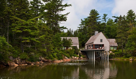
ARCHITECTUREIt Takes a Village: 2 Homes Made of Multiple Structures
Separate buildings join in style and intention in these home bases, showing that sometimes more is just right
Full Story
CABINSHouzz Tour: Log Cabin on Puget Sound Has More Room to Spare
A family’s 1940s beachside home on Washington’s Camano Island gets a wheelchair-accessible bathroom and a guest bedroom
Full Story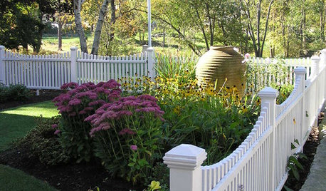
CURB APPEAL7 Great Structures for an Attractive Front Yard
Create a tasteful tableau for all to admire with a fountain, gate, statue or other eye-catcher
Full Story
HOME TECHWhat Chipotle and Radiohead Can Teach Us About Sound Quality at Home
Contemporary designs filled with glass and concrete can be hostile environments for great sound quality. Here's how to fix that
Full Story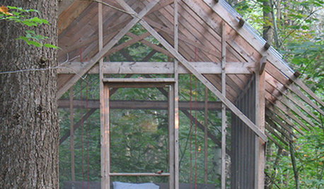
10 Small Structures That Whisper of Wonder
Stripped to their essence, these architectural outposts leave plenty of room for imagination
Full Story
ARCHITECTURECliffside Homes Encourage Living on the Edge
Thrills are everyday affairs even in structurally sound homes on slopes and cliffs, thanks to jaw-dropping views and unique configurations
Full Story
LANDSCAPE DESIGNPorch of the Week: Covered Deck Becomes a Glassed-In Retreat
A design-build firm blocks wind gusts from Puget Sound, in Washington, extending porch time for these homeowners
Full Story
3onthetree