Software
Houzz Logo Print
one_heart

Help with Front Entry Portico

7 years ago
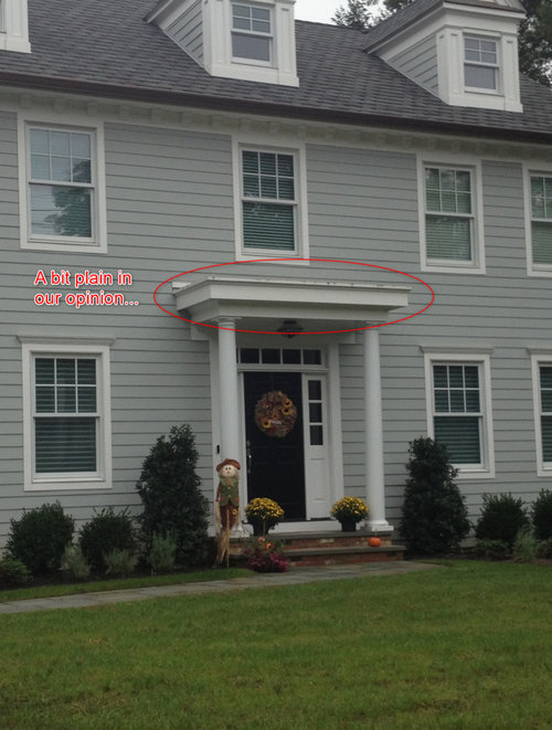
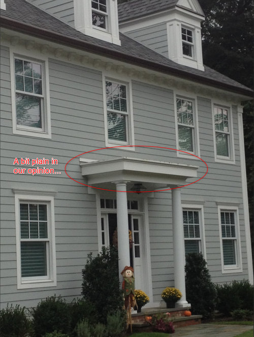
We recently built a traditional colonial home in New Jersey.


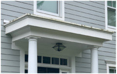
We don't think the builder implemented the front entry portico in the best way possible.


In our opinion, the front entry portico is a bit "dull" and "uninspiring".


What are the community's thoughts regarding ways in which we might improve the look of the front entry portico?


Note: the light fixture in the front entry portico is just temporary. We ultimately plan to buy the following light fixture:


https://www.brasslightgallery.com/P/337/LondonLantern12WideChainHungExteriorPendantLight


Thanks!

Comments (52)

  • PRO
    7 years ago

    last modified: 7 years ago

    Hmm. You'll have a bit of a problem re-designing due to the window directly above it. Did the builder use an architect for the original plans? If so, you might want to have a conversation with him.


    The only way you could enhance the importance of the portico might be to extend it forward, giving you a deeper overhang.


    Front Facade · More Info


  • 7 years ago
    last modified: 7 years ago

    We're not looking to do any major redesigns. What's there, is there. We're not looking to extend it upward or outward.

    My thought was to add some dentil molding similar to what is directly below the roof soffit. Perhaps something like the following:


    Thoughts?

  • PRO
    7 years ago

    Not sure you have room for a peaked roof on the portico, hence my comment on the window above. But you could certainly ask your builder.

  • 7 years ago

    We are not planning to change the dimensions of the portico in any way (note: it would most definitely violate the building code if we were to extend it outward). And, we don't want a peaked roof. At this point, we are only considering ways to improve the portico cosmetically.


    Thoughts on molding?

  • 7 years ago
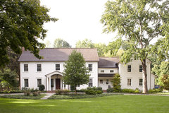
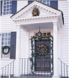
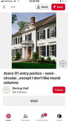
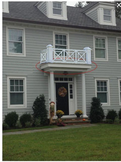
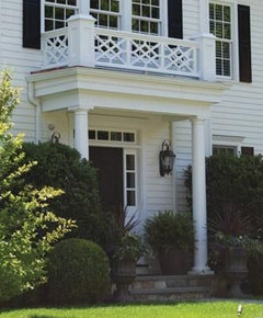
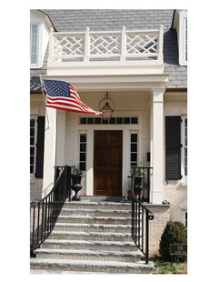
    What about something like these pics?
  • PRO
    7 years ago

    You can simply add a Chippendale railing detail to the canopy.


  • PRO
  • 7 years ago
    last modified: 7 years ago

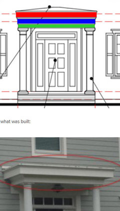
    Your designer and builder attempted to imitate a classical trabeated (post & intel) portico without doing their homework. The designer came closer than the builder so you might be able to get him to fix it.

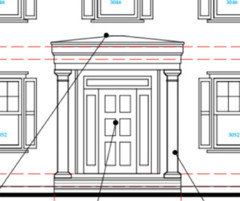
    Here is what the designer drew:


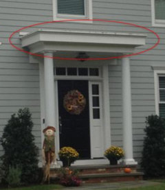
    Here is what was built:


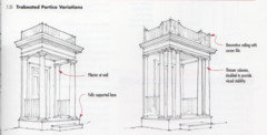
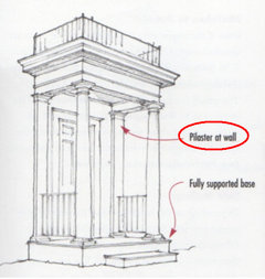
    Here is an example of a well proportioned trabeated portico from Get Your House Right by Marianne Cusato.


    Dentils could be added.

  • 7 years ago

    From the op: "We're not looking to do any major redesigns. What's there, is there. We're not looking to extend it upward or outward."

  • 7 years ago
    last modified: 7 years ago

    I think fixing this is important enough to justify doing whatever is necessary. Its the most important feature on your house.

    If you want to do it the least costly way, you might be able to add a large crown molding to the upper 2/3 of the cornice (that big fat blank board at the top) and extend the roofing to cover the top of it. You could also lower the bedmold under the overhang and add dentils but that might make it more obvious that it need to be taller.

    Can't hurt to mock all of this up to see how it looks.

    I would tear it all off and make it a really handsome feature. Its a days will for a good carpenter but it might take a week if you use the same one.


    Equanimity thanked User
  • PRO
    7 years ago
    last modified: 7 years ago

    At some point you have to ask yourself, "Is the money I spend to change this worth it, or can the money be spent better elsewhere?"

    Look at the existing condition in context with the entire structure's design. "A bit plain" may be what the exterior demands, in a good way.

  • 7 years ago

    @Mark Bischak - that's a fair point. The house is brand new and we're generally happy with the way that things turned out (both interior and exterior), with the exception of that front entry portico.

  • 7 years ago
    last modified: 7 years ago

    Instead of agonizing over the unknown, design a solution and get a real proposal.

    The resale value alone would justify fixing this ugly thing.

  • 7 years ago

    RES- thank you for that suggestion.


    For the front entry portico, the architectural plans showed "LEAD COATED COPPER ROOFING AS APPROVED BY OWNER". You can see from the plans that the roof had a slight slope to it. We decided to change that to a flat roof so that the slope was not visible from the street.


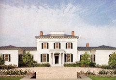
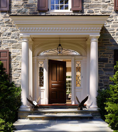
    We wanted something like this:


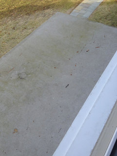
    So, the roof of our portico was done in fiberglass. It looks like this:


    The builder said: "I have been using that for flat roofs for 23 years without any issues."


  • 7 years ago
    last modified: 7 years ago

    By the way, in every jurisdiction I have worked, cornices are allowed to extend into a front yard setback 12" or more and roof eaves can extend even farther than that.

    I've never seen a flat roof or a specification for one. A roof should slope at least 1/8" per foot just to avoid puddling or water standing against the wall flashing. Low-slope roof slopes 1/4" per foot. Such a low slope cannot be seen from the street. Standing water will destroy anything; all building surfaces must drain.

    The bright wall flashing is just as annoying as the truncated portico. That's where you could have used lead-coated copper if its still allowed. Revere's Freedom Gray is a safer alternative with a tin-zinc coating on copper.

  • PRO
    7 years ago

    "I have been using that for flat roofs for 23 years without any issues."

    Reminds me of what the guy thinks after jumping off a 100 story building as he passes the second floor, "so far so good".

    Not to mention you did not get what the plans specified and possibly paid for.

  • PRO
    7 years ago

    Well...since you didn't get what the elevation drawings show, have you asked your builder for an explanation? A refund? A re-do? Anything...?

  • 7 years ago
    last modified: 7 years ago

    OP since you changed the plans and took away the slope it looks like you got what the drawing showed. Per OP "You can see from the plans that the roof had a slight slope to it. We decided to change that to a flat roof so that the slope was not visible from the street."

    The picture you posted above of what you wanted should have been communicated in planning as that is clearly not what is in the drawing. The portico drawn was never as substantial as you wanted. It appears the only difference is the removal of the slope, therefore you got what you approved.

  • PRO
    7 years ago

    Well...you better go back and look at the elevation drawing again. The as-built and the elevation drawing are completely different, without considering the roof at all.


    I'm wondering if tiggerlgh was the builder...that would explain a lot of things.

  • 7 years ago

    No, tiggerlgh was not the builder.

  • 7 years ago

    @ Virgil Carter Fine Art - you say that the "as-built and the elevation drawing are completely different, without considering the roof at all."


    In what way(s) are they different?

  • PRO
    7 years ago

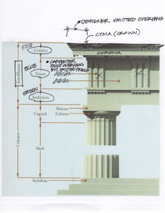
    See the red, blue and green parts? Find all 3 on your house.


  • PRO
    7 years ago

    Look on the bright side, they didn't give you the shutters that are shown on the drawings either.

  • PRO
    7 years ago
    /\/\/\ how hard is it to spec the right size shutter? Match the window height, divide the width in half. Done!

    Regarding the portico, you would have been happier if you had the builder build what had been designed. The current portico is too flat and insignificant. A balustrade would help but can be tricky to get the details correct and it will require new waterproofing on the roof surface.
  • PRO
    7 years ago

    I'm not up on all the correct period details, but a pilaster would help define the space.


  • PRO
    7 years ago

    It's not simply that there are three elements above the columns (which there are), but it's also about their comparative width, and how they relate to one another along their exterior profile.


    The OP's as-built has no resemblence to the drawings. Simply compare!

  • 7 years ago
    last modified: 7 years ago

    @Virgil Carter Fine Art, @PPF. and others --

    I'm going to speak to the builder about this and I would like to make sure that I fully understand how the builder's implementation deviated from the architect's drawings.

    PPF. included the following:


    Do the red, green and blue elements above the columns have technical or industry terms associated with them?

    Also, can you explain a bit more about what exactly is wrong with the "...comparative width, and how they relate to one another along their exterior profile."?

    Thanks!

  • PRO
    7 years ago

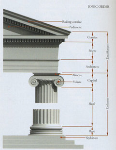
    Do the red, green and blue elements above the columns have technical or industry terms associated with them?

    If you look at the classical Greek orders, (this is one of several)


    you will find names for the various parts.

    Note how the architrave rests on top of the capital, and how yours is different.

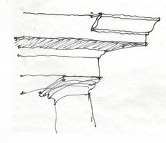
    Also see how on your roof, how one part overhangs the one below (shown below). Note in the elevation you posted, and in the image just above, how the transition from the green to blue to red parts is rather gradual.

    Getting scale and proportion correct is key.

    Equanimity thanked PPF.
  • 7 years ago
    last modified: 7 years ago

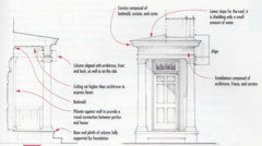
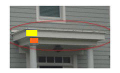
    The parts of the portico above the column capital (the Entablature) are described in my earlier post with drawings from Get Your House Right.

    Here is another drawing with the parts named with the relevant colors and notes describing what the designer and the carpenter omitted.

    Perhaps the carpenter was worried about the proximity of the window sill and the high point of the roof but it doesn't look like a problem to me.

    I know of no other names for the parts of classical Roman construction.


    Equanimity thanked User
  • PRO
    7 years ago

    PPF and RES have posted excellent illustrations of the three elements in question: Cornice, Frieze and Architrave. Note that the Cornice projects beyone the Frieze and Architrave, while the Frieze and Architrave essentially alighn, but with the Frieze slightly inset.


    Also note the relative proportions (heights) of the Cornice, Frieze and Architrave compared to one another. Clearly, the Frieze is the largest (tallest), followed by the Architrave, with the Cornice being the smallest height of the three.


    There are some differences in these elements in Greek and Roman Orders, but the point for your house is that your elevations depicted and illustrated all three elements--Cornice, Frieze and Architrave--but your builder chose to only fabricate and incorectly install the Freize and Architrave. The Architrave is substanially recessed behind the face of the Freize. The Cornice appears to have been lost when the decision was made to install a flat roof.


    Can you see all of this?


    I think it's repairable if you show your builder the illustrations from PPF and RES...assuming he is agreeable to making the needed changes and improvements to his work.


    Good luck.

    Equanimity thanked Virgil Carter Fine Art
  • PRO
    7 years ago

    "Entablature" . . . its all coming back to me now.

    Equanimity thanked Mark Bischak, Architect
  • PRO
    7 years ago

    One of the challenges in correcting and improving this is that the stylobate is too small and won't allow the columns to be wider spaced to match the existing entablature...always coordinate your stylobate with your entablature. The Greeks and Romans would approve...

  • 7 years ago

    We appreciate everyone's comments!


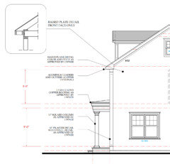
    Here is the side elevation:


    @Virgil Carter Fine Art mentions that "The Architrave is substantially recessed behind the face of the Freize".


    Is it fair to say that the builder constructed the portico in the manner that was specified by the architectural plans? (and that the only deviation is the missing Cornice)

  • PRO
    7 years ago

    Note the top of the column, and the architrave just above. I imagine the right elevation should match the front.

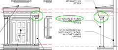
    I also see the square columns were specified.


  • 7 years ago

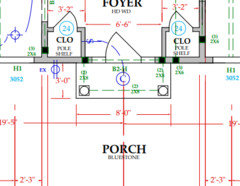
    Yes, it appears that the front elevation does not match the side elevation! And, yes, the builder installed round columns instead of square columns. Here is another view:


    It appears as though the columns are specified as ROUND in this view. But, I might be reading this incorrectly.


    Also, did the builder omit the Frieze or the Cornice?

  • PRO
    7 years ago

    I'd say the frieze is missing but don't think it matters. It's not built according to the plans which seem to have been followed elsewhere.

  • 7 years ago

    The frieze was omitted possibly to keep the roof as far as possible from the window sill I'm not sure that was necessary but you and/or the designer should have been consulted about the change.

    The cornice overhang and crown are missing because they were not shown on the design drawings.

    I think the simple solution is to add a large crown and extend the roofing over the top of it. The other option is to remove the top half of it and rebuild it.

    These issues are all described in my earlier drawings.

  • PRO
    7 years ago

    It's amazing to me that something so important as this portico has no dimensions, notes, not to mention, no enlarged details on the drawings. Just amazing.


    That said, there's no reason I can think of that the builder built what has been shown.

  • 7 years ago

    The builder has finally responded with:


    "It is built as per the side cut on the elevations and as per the framing specification.


    The front elevation had no specifications as to the details.


    The crown could be considered the 3rd layer."


    Are any of his comments valid? Or, is this an attempt to deflect blame?

  • PRO
    7 years ago

    "It is built as per the side cut on the elevations and as per the framing specification.


    Anyone can see that's incorrect, although we have not seen the framing specification, or any additional details -- if there are any, that refer to the porch.

  • 7 years ago

    @ PPF. - there are no additional details. In which way(s) wasn't the portico built according to the side cut?


    I believe this is the framing specification:


  • PRO
    7 years ago

    The differences are all well covered above.

    Equanimity thanked PPF.
  • 7 years ago

    The builder indicates:


    "The crown could be considered the 3rd layer. "


    Is there any merit (or truth) to this comment? Or, is this guy full of crap?

  • 7 years ago

    The details are difficult to see in the low resolution photo but if there is crown molding under the overhang it would be further evidence of the contractor’s ignorance. A crown molding belongs at the top of the cornice.
    What you need is a scaled section drawing so we can offer real solutions. That’s what should have been in the drawings in the first place and it’s the only way you will be able to fix this problem.
    If that’s too difficult take a better photo and note the dimensions on it. It shouldn’t be difficult to make this thing look better.

    Equanimity thanked User
  • 7 years ago
    last modified: 7 years ago

    Here is a more detailed photo. It looks like there is crown molding under the overhang:


  • 7 years ago

    I will post dimensions tomorrow.

  • PRO
    7 years ago

    Equanimity -- How may we help you? What outcome would you like from this conversation?

  • 7 years ago

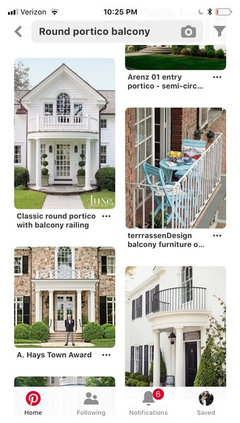
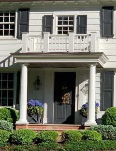
    @PPF. -- here is what we are trying to achieve:


    And, perhaps with a low-profile roof that looks similar to the following (but without the balustrade):


    What I would like to ultimately understand is whether this is achievable with what we have? Or, will something like this require "major surgery" (e.g. tearing the whole thing down and starting over)?


  • PRO
    7 years ago

    I would say that something similar is achievable without a tear down.


    Have you considered consulting a local craftsman? Maybe someone who normally works on older homes.


    You might want a full size mock up developed of one corner so you could see how it would look, or a 3D rendering showing a proposal. This one was done as an exercise so I'm not suggesting anything, just showing how it's helpful to visualize how a project might look when complete.


Sponsored
Hope Restoration & General Contracting
Average rating: 4.7 out of 5 stars35 Reviews
Columbus Design-Build, Kitchen & Bath Remodeling, Historic Renovations