Software
Houzz Logo Print
barnaclebob

Modifying a Range hood for more fan control (Zephyr)

10 years ago

Has anyone tried modifying a range hood, specifically Zephyr, for more fan control? After a few months I find myself wishing that the lowest setting was about half of where it is while keeping the highest setting where it is. The other middle settings would ideally be graduations in between the new low and the old high.


There must be a way to do it and I'm not afraid of messing with circuitry, soldering, or voiding warranties, I'm just not sure what to do.

Comments (26)

  • 10 years ago

    How many wires (conductors) are connected to the fan motor?

  • 10 years ago

    read the plate on the motor to match your new variable rheostat switch for infinite control.

  • 10 years ago

    May be use a laptop style volume control keys. I am zero knowledge about circuits. But one of those volume control keys can be found in older HP laptops.

  • 10 years ago

    uh uh. If you use circuits above a heat source you be making toast (ed circuits).

  • 10 years ago
    last modified: 10 years ago

    The current hood has circuitry and does not get too hot anyway.

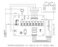
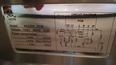
    Here is the wiring diagram:

    I don't want to install a separate rheostat because then I would have two controls to work. Is there anything to splice onto the motor connections which will reduce the current/voltage on the low end but keep the max current/voltage the same. I suppose a microcontroller could do the job but I'd have to figure out how to do that.

    I believe the hood motors have a "soft start" feature as well because they kind of slowly power up over a few seconds. Not sure if that matters.

  • 10 years ago
    last modified: 10 years ago

    First it is important to know that some ac motors do not "like" to be run at too low a voltage. Hence, schemes to lower the voltage at the low end may not be wise.

    Second, this system appears to be based on computer controlled induction motors (note that they are in parallel, so if a regular motor "rheostat" semiconductor phase controller were used (and could be used), only one would be needed).

    Third, unlike some induction motors where the other phase is induced, the other phase winding appears to be permanently connected to capacitors. This doesn't preclude "rheostat" semiconductor phase control, but I don't know all the boundaries for acceptability.

    Fourth, we don't know without some measurements on your part (you do have an oscilloscope, of course) whether all that computation is just setting a voltage, or is actually synthesizing a waveform that changes frequency with speed. Frequency control would allow an easy soft start. In this case, you would need to modify something (possibly hard encoded) to allow the low speed setting to operate at a lower frequency than it is programmed to run at.

    Fifth, a wiring diagram is not a schematic, so a lot of unknowns are in play.

    From a circuit modification point of view, a bag of worms you may have.

    The simplest thing I can see to do would be to add a switch to one motor's drive wiring (in series with the blue lead, say) to disconnect power to that motor. That would cut the air flow rate in half for any control setting, and probably (!) not cause any damage to the drive circuitry -- at least if it were only toggled with the fan power off. I don't know what would happen if one fan were at full power and the other fan then enabled. I wouldn't trust the circuit designers to design against circuit damage due to the equivalent of an intermittent motor power lead.

    Other circuit configurations come to mind that might be amenable to modification, but I have too little information to make a suggestion.

    kas

  • 10 years ago

    My work is done

  • 10 years ago

    Old school. I like it.

  • 9 years ago

    Hey kaseki, can you elaborate on your suggestion for putting a switch in to turn one fan off please? This is exactly what I have been wanting to do on my zephyr range hood. I want to modify the fan so I can run one or the other or both fans.

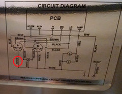
    My thought was to install a spst switch on the hot wire to each fan. However when I opened it up I realized that the speed control is set (of course) before the lines split to power each fan. My fans each have a yellow (capacitor), white (neutral), brown, blue, and black wires. I think the brown, blue, black each run to a different location on the winding of the motor, correct? That's how the speed control is done?

    Can I switch just one of those (on either Fan's side) to disable that fan?

    If so, can you explain why that works? If I switch the blue, won't the black and brown still be able to run the fan on whatever setting they power?

    What if I interrupt the neutral wire with a switch? I know that's bad but I am not totally clear why it would matter in this particular circumstance.

  • 9 years ago

    Aaron King

    So your motors are wired in a different way than shown in the wiring diagram of barnaclebob's post? More is needed. For example, do you have a simple three position speed switch connected to the motor, or is there also a processor? Or a soft start scheme?

    For lowest risk without more information, I would recommend a three-pole single throw switch in series with the brown, blue and black wires. With this configuration, which might seem to be the same as just switching the white wire, you could avoid possible currents between those color wires as well as avoid induced currents circulating in the capacitor loop if the electronics were to provide voltage to more than one of the brown, blue and black wires at a time. If you have only a rotary switch controlling the three wires, then such currents should be unlikely.

    Something I didn't mention earlier, but should have, is that dual fan configurations typically service different sides of the hood aperture. When only one side is running, the other side MAY not successfully perform containment of captured cooking plume effluent that rises into that area. Of greatest concern would be middle burner cooking plumes, as low performance on the off side might be expected and cooking performed appropriately.

    If the hood has narrow height containment volume behind mesh filters, the pressure loss from the filter and from horizontal transport in the volume may average out the flow over the entire space, avoiding the consequences of the above paragraph.

    kas

  • 9 years ago

    Thanks for your thoughtful response. Its got a single button that cycles lo, med, hi, not rotary. There is
    a capacitor, but I am not sure it's function.

    Wiring diagram attached.

    Can you explain how speed is controlled here? Do the 3 wires just energize different parts of the motor windings? Or do they provide different current or voltage?

  • 9 years ago

    Capacitors are used like a starter on your car to get the electric motor up to a certain force and rpm before retiring from the work.

  • 9 years ago

    They are three speed motors.

    The blue wire is HI, brown is Med, black is Low.

    If you switched the neutral (white wire) the fan will not run.

  • 9 years ago

    You could try interrupting the white wire to keep a motor off while letting the other motor run, but the off motor should be felt at intervals to ensure that there are no currents between windings in the motor that could be heating it while it was static. If the motor doesn't stay off for all switch settings, or heating occurs, then the yellow wire for that motor would have to be interrupted also with a 2PST switch.

    With this motor design, I expect that there are three motor windings having different pole counts intended to cause the motor to "near-synchronize" at each of three different speeds. Alternatively, the PCB may be generating different frequencies. I cannot say whether the provided voltages are the same for each. A fourth winding likely connects to the capacitor via the yellow lead. This winding is designed to generate a secondary field that the field from the energized winding attempts to catch up to (or run away from), which it can't, so the motor continues spinning. Induction motors do not need second phases to keep running under light loads, but they do for starting, and the the second phase, if continuously on, allows more torque to be generated.

    This feature underlies a method for providing three-phase power for tools in a single phase residential power home using a larger three-phase motor as a motor-generator.

    For more on induction motors, see:

    http://www.explainthatstuff.com/induction-motors.html

    https://en.wikipedia.org/wiki/Induction_motor

  • 9 years ago

    Well, I don't want to run the risk of overheating anything or having errant currents running about if I just switch the neutral. I'll switch all 3 hots (blue, brown, black) with a 3pst on each fan. I ordered a couple already. They are not the very slick-looking push-buttons I wanted to use, but oh well. They are stainless steel bat-toggles, simple, and easy to replace, and i will put them in a less-conspicuous location.

    Other option was to use my nicer buttons to control 3pst relays on each motor, but they are really expensive.

    Now, what about the yellows coming from the capacitor? Will those be energized? I still don't understand how the capacitor is working here. i understand that it is used as a starting current, but how does it function?

    The only connections are a yellow to each motor and a white going back to the common neutral. So, it can't be supplying voltage, right? Its neutral, no voltage.

  • 9 years ago

    There should be no current in the capacitor circuit if all three power leads are interrupted.

    The penultimate bottom line here is that from this distance it is difficult to estimate the circuit design without either a real schematic (including the PCB) or measurements taken for each switch position. So it is best to do what is certain to work -- interrupt all power leads as you plan.

    kas

  • 9 years ago

    Thanks! Will do.

    So what does happen with those yellow wires that go to the capacitor? Does current only go on those when the motor starts up? How does it know when to stop sending current into the capacitor?

  • 9 years ago

    I expect in this case that current to the motor from one of the three darker color wires goes through a winding to the white lead, but also to a winding to the yellow lead and thence to the capacitor, so the capacitor is always powered if the motor is powered. However, there are motor designs with centrifugal switches that switch out the starting cap when the motor rotates fast enough. Insufficient data still holds here. A measurement is worth 1000 of my guesses.

  • 9 years ago

    Oh, interesting. So, lets say, with whatever mechanism, some of the current goes through the yellow and then to the capacitor. What function does the capacitor have? What does it do that has an effect on the motor?

  • 9 years ago

    I think I explained that in the response just below geoffrey_b's message with the wiring diagram.

    I expect that if one probe of a differential oscilloscope were connect to a dark color wire that is powered at a given switch position, and the second probe were connected to the yellow wire, and the 'scope was operating chopped at some appropriate sweep rate for showing a few cycles of 60 Hz, there would be a decent phase shift between the active dark wire and the yellow wire.

  • 9 years ago

    I have a Zephyr range hood and the fan has speeds 1-5 (IIRC), and then the top speed is called Burst Mode. When they installed the hood they had to jumper the motor to allow the speeds higher than 400 cfm, after verifying there would be sufficient make-up air. Bottom line - it is very configurable. Have you contacted Zephyr to find out if they have some way to modify the fan speeds?

    Bruce

  • 9 years ago

    Kaseki,


    So the capacitor induces a phase shift in the separate winding? I need to go read about capacitors. I thought they were just short-term batteries.

  • 9 years ago

    For dc applications, one might think of capacitors as having some battery like properties -- generally less amp-hr capacity than a battery, but lower series resistance. In ac applications, a capacitor (left to itself) provides a 90-degree phase shift to the relationship of current vs. voltage. In EE terminology, the relationship of voltage to current is the impedance, and passive ideal components are characterized as: resistors (Z = R), inductors (Z = wLj) and capacitors (Z = 1/wCj) where Z is impedance, w is natural frequency (2pi f) and j represents the square root of minus one; R, L, and C are resistance, inductance, and capacitance, respectively. The use of imaginary numbers relates to the imaginary exponential definitions of sine and cosine, or alternatively, the use of vectors in the complex plane to represent phase and magnitude. Combinations of these components can provide various frequency dependent voltage vs. current functions. Even more potential for voltage vs. current functions exist when the components are used within active circuits.

    In other words, even the most basic aspect of electrical engineering is more esoteric than one might imagine.

    In the motor circuit, the purpose is merely (!) to shift phase. I expect that capacitors have been performing this function since before vacuum tubes were developed for amplification in radios. Large single phase motors not needing capacitors were used a century ago, e.g., induction repulsion type, but I think they have fallen out of favor, or are only used where the capacitors would need to be monstrous. Most industrial areas of the US have three phase power these days, so capacitors are not needed for large motors because the three phases already provide the necessary phase shift. Tiny synchronous motors as used in clocks directly wired to electricity use a different no-capacitor technique to shift phase -- I think I've seen a description somewhere on the Internet.

    kas

  • 9 years ago

    So the higher the impedance (distance between plates, if i understand how they are built), the lower the capacitance.

    Does capacitance describe the amplitude of the phase shifted current relative to the original current? If I put an ammeter on the neutral wire leaving the capacitor, and another on the neutral wire laving the motor, and charted those values, I would see 2 sine waves, offset 90 degrees, with the amplitude of the capacitor wave equal to a function of the original motor current and the resistance across the capacitor (and some constants)?

    Is the phase shift always exactly 90 degrees?

    thanks

  • 9 years ago

    Cart vs. horse. A two plate capacitor has a lower capacitance the farther the plates are separated, and hence a higher impedance. Modern capacitors have plate separations measured in microns, in some cases.

    The 90-degree current result would occur if the only network elements being compared were a straight wire and a capacitor. Once winding resistance and inductance are accounted for, the phase shift can be different. It doesn't need to be exactly 90 degrees for the motor to chase its tail.

    This is not the right venue for illustrating the math. I'm sure Wikipedia has some basic overviews. When the entire circuit is evaluated, using the impedance values I described for the various parts, and the ratio of the capacitor's impedance to the entire path impedance is calculated, the magnitude of the result relates to the resulting signal magnitude and the ratio of the imaginary part to the real part relates to the phase. "Relates to" is to be interpreted loosely; you will have to look up complex math.