

Cantilevered addition?
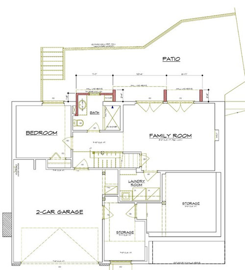
We are planning to bumpout our top floor by 2'4" deep and 17'3" long over our back patio. Our back lot is sloped so the patio is supported by retaining walls. The designer has given us a plan that uses stub walls to support the addition. He thinks these supports will be far less expensive and complicated than cantilevering the bumpout. The house was built in 1950 and I don't know which way the floor joists go.
Opinions on whether this is really the best option? We may be willing to pay more for it to look better but I have no idea how much more. We thought about building out the lower floor to the same dimenstions but it creates a really awkward family room for us. And we can't extend the bumpout all the way to the corner of the house due to our wedge lot shape and side setbacks. So the addition has to be stepped in.
Thanks for your feedback!
Comments (24)
 10 years agolast modified: 10 years ago
If you think about it, basically what they recommend is using support pillars to hold up the structure, similar to a deck. If that doesn't bother you it would be the easier route. If you want to cantilever, you have to modify the existing structure to do it correctly. Or wall brackets as mentioned. Going the support pillar route they should go down to a proper footing of course.
Related Professionals
Pittsburg Home Remodeling · Kansas City Home Remodeling · Saint Joseph Home Remodeling · West Plains Home Remodeling · Elizabeth City Home Remodeling · Raleigh Home Remodeling · Ardmore Home Remodeling · Nashville Home Remodeling · Anderson Kitchen Remodelers · Peoria Kitchen Remodelers · Toledo Kitchen Remodelers · Emporia Bathroom Remodelers · Lawrenceburg Bathroom Remodelers · Martinsburg Bathroom Remodelers · Oshkosh Bathroom Remodelers
dominos
Original Author10 years agoVith - Will we need a footing even with the stub walls he has drawn? Will that involve ripping up my flagstone patio or building on top.
Wall brackets sounds ideal to me - less blockage to my french doors and leaves the patio open. Are those really an option?
But a support pillar is second choice - you mean like a column?
JDS - Do you mean find the original house drawings at the building dept to look at the floor?
- 10 years ago
Wall brackets sounds ideal to me - less blockage to my french doors and leaves the patio open. Are those really an option?
Yep
[https://www.houzz.com/photos/detail-view-of-structural-brackets-supporting-balcony-traditional-exterior-minneapolis-phvw-vp~944693[(https://www.houzz.com/photos/detail-view-of-structural-brackets-supporting-balcony-traditional-exterior-minneapolis-phvw-vp~944693)
- 10 years agolast modified: 10 years ago
Yes, the original permit drawings should show the framing of the second floor. Its public information; just ask to see the folder for your address. They may have to find the drawings but more recent drawings are on disk.
The walls would require foundations so they might be the most expensive way to do it. The brackets coould be a 45 degrees so they are only 2-4 tall or they could be the height of the wall.
 PRO10 years ago
I would try to pull your cantilever back to an even 2'-0" if possible.
Depending on how your framing runs, you may be able to remove a portion of your
finish/sub floor on the second level and cantilever new joists against the old, out beyond your existing wall, then rest the new framing (walls & roof) on top of that.In reviewing your plan, I am
'guessing' that your existing floor joists already run front to back, so
you should be able to bolt and block additional framing to the joists
already in place (8'-0" + feet back into your room). I can't read the dimensions on your drawing, and don't know what size joists are already in place, so this may or may not be a possible solution, but it is something to consider under the right conditions.
When you remove your rear wall, you will need an overhead girder or beam as well, to carry your existing framing, and possibly your new roof, depending on the direction you run your new framing in, so make sure that you have the bearing below to track the load down into the foundation on either bearing end.
Good luck! Marcydominos
Original Author10 years agoThanks Marcy! Yes I have a feeling the floor joists do go the way we want.
Why is it important to remove the extra 4"? The bedrooms above really need the inches - they are tiny.
So I understand that in order to cantilever we need to remove 8 feet back into the subfloor and I think it is likely possible to do so. But the designer felt it would be very expensive?? Any idea what cost multiple cantilever vs. stub walls is?
Which option do you think is best - walls, cantilever or the brackets suggested above?
- 10 years agolast modified: 10 years ago
I would consult with an engineer on this, and get them to design the support system. Especially if you have soils issues, wind or snow loads, or earthquakes. In fact, I would get the engineer out to look at the house, to look out for any issues that might be made worse by the cantilever.
dominos
Original Author10 years agoThanks scone911. An engineer will for sure be involved. We just don't want to head down a path in the drawing phase that we will have to rethink later.
- PRO10 years ago
@Domino's .... 24" is the standard in most cases. Once you exceed that dimension, wall bracing may be effected.
I thought I'd mention your cantilever condition, because in reality, there are variables involved that you should check. The variables include loading, joist size and o.c. spacing, the weight of the wall + roof at the end and your method of framing (the direction your overhead roof will be running?: (right to left or front to back)) Due to the fact that you will probably be adding a second beam overhead, I suspect the only roof load you will be carrying will be that of the new addition and the roof span direction in which you run that roof will determine how the new loads will be applied to the cantilevered area below. Either way, this is a question that should linger in your mind because it is cheaper to adjust your dimensions before the fact than after you've been shot down by the building inspector.
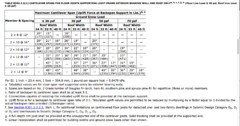
Refer to table R502.3.3 (1) in the IRC 2012 Code Book. You can probably google it.
Depending on your variables, interpolation (should you fall between the guidelines) is allowed. Too, you should be able to verify your allowable maximum cantilever with your local building official once you have your numbers together. In most cases, they will be happy to help you determine the codes correctly.
As far as costs goes, I don't know which would be the cheaper or more practical route for you to take. But I do wish you the best of luck in achieving your goals.
- 10 years agolast modified: 10 years ago
24" is not the standard and the building inspector will not tell you how large the cantilever can be; that is up to the structural engineer. Residential building codes have structural provisions for cantilevered floor framing that has not been designed by an engineer. The backspan must be 3 times the cantilever and the maximum cantilever is determined by a table for a given dimensioned lumber joist size and spacing. The cantilever lengths vary from 15" to 48". An engineer will not use this table but instead calculate the size of the cantilever using stronger framing like LVL's or steel.
A structural engineer is the first person to consult rather than the last. I suspect he/she will tell you to remove the ceiling below rather than the flooring above. The engineer will inspect the joists when the ceiling is open (make a small hole first) in order to verify the design that was submitted for the permit.
The drawing you posted is inadequate for anyone to give you structural advice. This is a 3 dimensional puzzle so your designer should have included a wall section and an elevation showing how the roof will be supported and/or reframed. That will probably be more difficult to do than supporting the cantilevered floor.
Why didn't the designer get the original drawings at the building department? Wing walls will require foundations which is obviously the most expensive option unless they are really just one story tall brackets disguised as walls. They should be rejected for the restriction of light and view alone.
Until you get an engineer or architect involved you're spinning your wheels.
- 10 years ago
Thanks scone911. An engineer will for sure be involved. We just don't want to head down a path in the drawing phase that we will have to rethink later.
Yep, I get it. Just know that it's often a non-linear process. Back and forth among various professions and trades, with the budget always shifting. Wait until your architect, engineer, contractor, and the building inspector start to duke it out. That's a barrel of laughs! ;)
- PRO10 years ago
@ JD, with all due respect ....
Let's start with the drawing that I posted???? What drawing is that?
Furthermore, I did not say that the building inspector would size the cantilever, although he may verify it. In my neck of the woods, our County Building Officials will help walk you through the codes and "help you to determine the variables correctly if clarification is in order. The way codes are written, they can be very confusing for most people with all of the exceptions and loading conditions involved.
Even then, the code section that I recommended to dominoe to use as an example of the varying cantilevers, based on the many variables involved, includes roof loading for the main house, which probably won't be a factor in this revision, since from what little information there is to go on, I am 'assuming' that the original roof load will be carried on a new additional beam overhead, rather than at the end of the cantilever itself. That leaves only the new roof to be taken into consideration, which given the side of the new punch out as suggested per this conversation, is going to be minimal.
The 24" cantilever I mentioned, was in reference more in regards to bracing methods, than not. Once the 24" is exceeded simplified bracing methods are out the window. These may not even be a factor since this is a revision, rather than new construction.
Either way, like you said, there are too many variables involved and not enough information to determine the cantilever, which is why I brought it up. The length of the cantilever should be questioned since in the original drawing revision (above) projected revision footings are in play to support the extension above. Once removed, the scenario changes.
I do agree that section cuts and elevations would help determine how the cantilevered extension would/will be loaded. And I do agree that an engineer should verify the final design once all of the factors have been taken into consideration.
It sounds to me like dominoe is unsure of what he wants to achieve at this point, so hiring an engineer now would probably be wasted money, in my opinion.
- 10 years agolast modified: 10 years ago
Sorry, unless someone addresses me or I address them by name you should assume I am speaking to the OP. I'm an old architect so my concern is always with the OP's question just as it would be for a client so I don't often chat with other members.
To clarify, if an engineer stamps the design drawings, a building inspector would only need to verify the validity of his/her professional license. Design by engineer is always preferred to design by building code tables. All that would be needed to make the tables useless is any unanticipated complexity. I would never use the cantilever table.
I really didn't understand your comments about limits on cantilever length or bracing methods nor do I understand why you would assume anything about the roof support.
Since the first and second floor walls do not fully align, lateral bracing would need to be provided by the parts that are aligned. But I doubt that is something that can be designed using the building code.
- PRO10 years ago
@JDS ... I designed roof trusses for 19 years, and I've done quite a few renovation drawings ahead of an Engineer. In most cases, beams don't need seals since all of the calculations are provided by the vendor and shown on their drawings along with all of the loading factors used to obtain the final reactions, deflection, and so on. In most cases the Engineering can be run on LPs website, then the output drawing, along with the plans showing the loading path is generally acceptable. If you don't have a full set of plans, then the building inspectors in my neck of the woods do want to see an Engineers stamp and they want a copy in their files. CYA.
As far as the roof support goes. We are talking about a newly exposed area of 2' out x 17' wide, give or take. That is really not that big of a deal as far as added loads go in building construction. Exclusive of the added wall weight, using rounded dimensions, and the following loading ... 20-10-30-10 to cover roof (LL in my area) + floor load (LL=sleeping) and average dead weight ( typical - assumed) in both cases, I come up with a total load on the (2' x 17' area = 34 square feet total) x (70' = 2,380# = Total Weight), exclusive of overhangs on the new rafters) and as mentioned earlier, the dead weight of the new exterior walls. That is not a lot of added load no matter which way you turn the roof.
These calculations are based on the ASSUMPTION that a new beam will be added overhead to carry the weight of the existing roof. I am using my imagination and commonsense since I have little else to refer to.
My intent when I left my original comment was to give domino a little food for thought and to alert him to the fact that variables matter.
As far as the wall bracing goes ... they are getting tough on it, and there are two methods that can be used: Simplified and Standard, IRC 2012 covers both methods in detail, with differences between the two. I doubt either method will apply on this particular job since it is a renovation job as opposed to new construction. But if the building inspector wants to make an issue of it, he can. Depending on where domino lives, seismic variables may apply as well. I live in Virginia, so here, we only have to worry about wind bracing.
Keeping the cantilever tucked back 2' or less remains within the guidelines of Simplified Wall Bracing. Since I don't have to deal with it, I am not sure if this is true in areas beyond Seismic Category B. If so, then this would be a factor to take into consideration, and again, can be verified though the local building inspector.
dominios, if you're still with us, I hope you can muddle thought the garble and pick up some useful information. Ah, decisions, decisions! :)
- 10 years agolast modified: 10 years ago
I don't know what this design has to do with trusses. The OP wants the addition to project 3 ft. so there is no reason to make it shorter. Your approach is unnecessarily complicated. I recommend hiring an engineer first and then reviewing the options with a contractor. Designing in a reverse sequence will only waste time and money. The current design is evidence of that.
- PRO10 years ago
@ JDS .... This design doesn't have a thing to do with trusses. You said you were an old architect, so I was reciprocating in the conversation. Thus I mentioned that I'd designed trusses. The more we converse, the more it appears that you simply like to argue. Go for it, I said what I had to say. This is dominoe's project, and I'm sure if he feels the need to hire an engineer, he will. If it were me, I'd visit with my building inspector/official ahead of pulling a permit and show him/her my paperwork and see if an engineer is needed at all. This addition is not all that complicated.
Out of curiosity, where did you come up with a 3'-0" dimension? Dominoe's opening statement, and I quote is, "We are planning to bump out our top floor by 2'4" deep and 17' 3" long over our back patio". I must have missed something along the way?
I also don't know what is so difficult about my approach. I thought it was pretty straight forward. If dominoe has any questions, he is free to ask me to clarify whatever it is that confuses him.
- 10 years agolast modified: 10 years ago
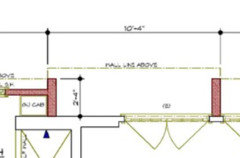
Your approach is to shorten the 2-4 and 3-0 cantilevers to 2-0 and remove a portion of the second floor finish and sub floor to add joists. It is entirely contrary to the OP's goal of maximizing floor area and minimizing cost to reduce the floor area of the new work and remove and reinstall existing flooring. I also believe it is much wiser to use a professional for structural advice rather than vendors, strangers or building inspectors. We simply disagree.
- PRO10 years ago
@JDS ... Well, I do agree that we disagree.
And I still don't see a 3'-0" Cantilever. I see where the bearing the original designer has shown using his/her new piers juts out 2'4" and I see a line with text over it beyond that, but can not read it. It says something about 'above' but that is as much as I can read. It looks like a dimension line to me? Maybe I'm wrong? Either way, if dominoes has followed our conversation, he is welcomed to pick out whatever parts he chooses to pursue.
In a situation like this with so many unknowns, I am merely tossing around options for him to contemplate, nothing more. If I were doing the job for myself, I would do it the way I suggested to alleviate having to disturb the footings or having to add more ASSUMING the existing floor joists are running front to back, perpendicular to the rear wall. But again, it is not my job.
Take care and be well.
- 10 years agolast modified: 10 years ago
The drawing note should be clearly visible on the original post and says: "WALL LINE ABOVE". I moved it to a lower resolution screen and its even easier to read there. The designer consistently uses a dash-dot line for features above the plane of the plan so the meaning is clear.
Your approach would reduce the floor area of the work by 30%. Removing the flooring instead of the ceiling might double the cost of the work.
The offset and staggering of the second floor wall as well as the likely need for LVL framing makes this a job for an engineer, not you, me, a vendor or a local building inspector. It is important to me that dominos takes that advice otherwise I would not be bothering with this discussion.
dominos
Original Author10 years agoOP here! While you guys lost me on the industry speak I really appreciate the help and feel I am better informed. I have communicated to the designer that we would prefer to talk to a structural engineer and explore cantilevering rather than assuming the "wing walls". He is working on elevations now...
Thanks everyone!
 PRO10 years ago
OP, Hope you got an earful :) of opinions & directions! Now on to solutions
 PRO10 years ago
Hire a Design Build Firm. Preferably one with an in house Architect. It may be worth the extra money because the Design Build Firm will be the best at value engineering.
They will inspect, at minimum.
1 The soil (samples)
2. footings/foundation (digging and drilling)
3. load capacity of the walls (pulling siding, drywall, flooirng, etc)
Take into mind the house is over a half of a century old, if you are in any earthquake or hurricane area, you may be faced with additional retrofitting requirements so the place doesn't fold like a book from the added weight during a natural disaster.
Also, I have never found a building department that has kept any plans a half century old. They don't even keep them from 10 years ago in my area.
There is also a miss information on an engineers stamp, a building department has the full right to check or send off to be checked any number, design or anything otherwise and approve or deny as they deem appropriate; it does not matter who it was stamped by or even when, if they feel or think there is an error example: you passed your framing inspection and they are there on your rough electrical inspection, the inspector can put the job on hold and have you correct a framing error if one exist at your cost even if it is built to the plans. If there is an engineer or architect involved, you can file a claim with there insurance most commonly there Error and Omission Policy for any losses.
We (a company I was working for) did a similar concept project at a resort but it was 10 feet on the third story, we immediately realized adding 10 feet all the way down was the most effective way in our case, as it also added a much needed 800 square feet to each of the 3 levels.
Best of luck,
Nicholas Mendoza
Greenspot Construction
HTTP://www.greenspot-construction.com
- 10 years agolast modified: 10 years ago
"There is also a miss information [sic] on an engineers stamp,"
In some states anyone is allowed to design the structure of a single family house and the building department will judge the appropriateness of that design. In other states a building department can only determine if a design meets the prescriptive requirements of the building code and is required to accept an engineer's stamp if the engineer's license is valid. In some jurisdictions a structural engineer is required for all houses.
These widely differing standards hinge on the collective opinion of the state legislature regarding who should be responsible for public safety in general and the structural design of a house in particular. Towns also differ regarding the responsibility their building department can take for the structural design of homes.
But state and local law are not the important issue here. When a cantilevered upper floor involves staggered and offset paths for lateral force resistance, the design cannot be adequately addressed by a building code, architect, builder or building official so it is wise to consult a structural engineer.





User