Software
Houzz Logo Print
heldmacm

Wiring Help Needed Reinstalling Ceiling Fan with Possible Loop Switch

9 years ago
last modified: 9 years ago
Hello,

I suspected one of my ceiling fans wasn't installed to a ceiling fan rated electrical box, and after removing the fan, I was unfortunately correct. I'm going to have an appropriate box put in, and then I intend to rehang the fan, but looking at the wires coming from the current electrical box is giving me some pause. I have two sets of black, white and ground wires, and based on what I've read online, I believe I have a loop switch. I don't know when this wiring was done, but in the event it helps the house was built in 1957.

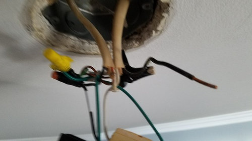
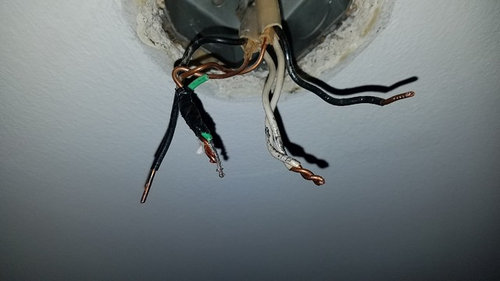
The below picture shows what I currently have in the electrical box with the fan removed. I have not untwisted any of the previous braided wiring other than what was necessary to remove the fan.

In the above picture, using a non-contact voltage tester with the power on, I got "beeps" from all wires (or sets of wires) with the exception of the two white wires braided together (the second from the right). With the power off at the box, none of them produced beeps.

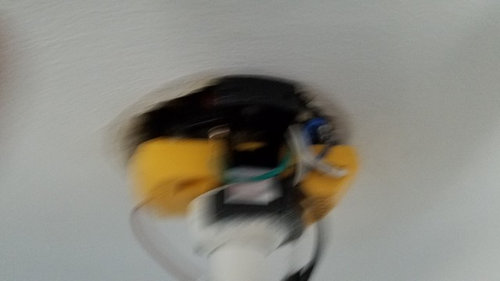
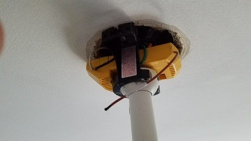
I tried to be proactive and take pictures of the wiring before I took down the fan, but unfortunately, those pictures turned out awful either due to forgetting to turn on the phone's flash and/or I wasn't holding the phone steady when taking them. I don't expect these will help much, but below are the pictures with the fan bracket and remote sensor still in place before I undid any wiring.


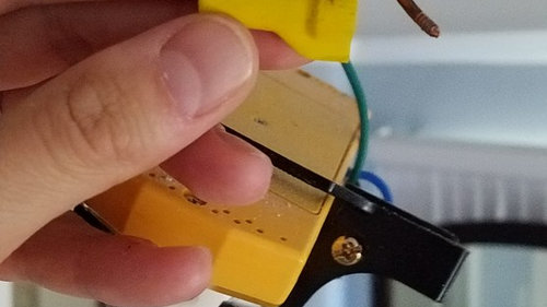
The below shows a wire that was previously capped / not connected to anything else after I removed the wire nut:

Anyway, I'm hoping someone can help confirm whether this is indeed a loop switch, and either way, what the appropriate way to connect these wires is once the electrical box is replaced. The fan has a set of black and white wires on one side of the yellow receiver that was (marked AC IN L and AC IN N, respectively) and a wire marked antenna that was not previously connected to anything (it's the one hanging in the pictures). On the other side of the receiver, there's a black wire (TO MOTOR L), white wire (TO MOTOR N) and blue wire (FOR LIGHT). There's also a green wiring hanging down from the downrod (that's not connected to the receiver) that isn't marked but I assume is a grounding wire, and I found a green pigtail connected to a screw (no markings, but I, as well.

As far as how I'd like the fan to work after it's reinstalled, I'd like it to work as it did before. Flipping the single wall switch turned on both the fan and light but only if both were previously on via either the pull chains or remote. If the fan and/or light were previously off when the wall switch was last on, they'll remain off the next time it's turned on. In other words, the last state is maintained when flipping on the wall switch. There aren't any other wall switches in this room; the only others are in the bathroom connected to this room.

I would greatly appreciate anyone's help with this. Thanks in advance, and please let me know if you have any questions about the above or need any additional information.

Comments (8)

  • 9 years ago

    What wires were the fan (or in your case the fan remote) originally connected to? The black on the left and the two neutrals in photo one?

    IF the capped off black (wire on the right) leads to your switch box, then I'm going to GUESS that you do have a switch loop, but one that was incorrectly wired and not being used by the current fan because it has a remote, which only requires a constant hot to function. In your case, it appears that the switch loop was switching the neutral and not the hot wire.

    I'm making assumptions based on what I see in the photos, wires need to be traced out to prove or disprove what I've stated.

  • 9 years ago

    I'm puzzled by the fact that your voltage tester beeped on both black wires. That suggests to me that you might not actually have a switch loop there, but rather two hot cables in the same box.

    Is it possible that one cable comes from the switch you're using now, and the other is from some other switch somewhere? Or even live all the time?

    Normally a fan and light combination will be wired with 3-conductor cable (red-black-white) with the light switch feeding power to black and the fan switch feeding red (or vice versa). White is the common neutral. But AFAIK it wouldn't be improper to have two separate cables coming from two separate switches, or one switched and one always hot.

    Non-contact testers are useful, but I don't fully trust them. I'd test those wires with something that actually draws some current. I like using a 15 watt or 25 watt incandescent bulb in a rubber pigtail socket for this. Adding an insulated alligator clip to the white pigtail wire is helpful.

    A neon glow tester would be OK as a substitute.

    Just be careful when testing with the power on, of course.

  • 9 years ago

    Voltage testers are known for false positive. If it's connected to an open switch and parallel to a bunch of other wires, it may not have been actually hot.


  • 9 years ago

    Get a better tester or use a voltmeter/multimeter on volts ac with prongs on black and whites to see which is live. I recommend the klein tools tester. I have also had a cheap brand one in the past that before I threw it away, would beep even when I had it held away from everything so yes they do go bad.

  • 9 years ago

    Thanks for the replies, everyone. It is certainly possible I'm getting false positives with this voltage tester. For what it's worth, it is brand new, as I purchased it exactly for this reason. The one I bought is linked below:


    https://www.amazon.com/Non-Contact-Electrical-Inductive-Multimeter-PM8908C/dp/B01AFQOM2U/ref=sr_1_2?ie=UTF8&qid=1508452056&sr=8-2&keywords=PM8908C

    To double check my initial readings, I turned off the power and flipped on the light, and none of the four resulted in any beeps. I then turned back on the power, left the light switch on, and I got strong beeping/light flashing when just touching both outside (black) wires pictured in the first picture in my initial post. The white wires that are braided together don't give off any beep, and the bare wires that are braided together and secured with electrical tape result in some beeping and lights flashing but not as pronounced as the black wires.

    I did manage to find the directions for this Harbor Breeze fan, and if I could safely figure out which wires go where, I'm reasonably confident I could make the below connections and get the fan back up:

    However, it sounds like what I bought isn't enough to accurately (safely) make that determination. If anyone else has any additional ideas how to identify my wires in accordance with the above directions, I'd certainly be interested in hearing them. Otherwise, I'll reluctantly have to hire an electrician to put this back up, as I really don't do enough work with electrical wiring to justify spending more money on a voltage tester. Thanks again.

  • 9 years ago

    I have a Harbor Breeze fan, with similar instructions. The receiver's red wire is connected to the power source, and its black and blue wires go to the fan's motor and light (I'm not sure which is which, from your description). The white and ground wires just go to the equivalent wires from the supply. The problem I had is (was) that my electrician had run separate wires from the wall switches to the fan box, expecting that the fan would be controlled by these switches. I tried to bypass the receiver in the fan, but could not get a wire down to the light (I didn't want to use the remote control). So, now, I have one wall switch and control the lamp brightness and the fan speed and direction all with the remote. I make these settings, then turn off and on the fan with the wall switch. I only need the remote when I change the settings.

    If you have a supply wire (black, from your picture) which is on or off depending on a wall switch, then you can use it like I did. If you want to use only the remote, then find a black wire which is always on.

    You need to figure out where all the black wires go. One is probably an always-on supply wire. One may be a switched supply wire, and one (which now tests no voltage), probably goes to another light or a receptacle. For testing this type of wiring, I use an incandescent bulb in a socket which has individual wires, like this.


  • 9 years ago

    Thank you, mtvhike - that was very helpful. So if I were to purchase one of those inexpensive bulbs that you provided a picture for, I would hook up the black and white wires to the corresponding wires from the box? Or is the white wire not even needed for the purpose of identifying the wires? Finally, how would I determine which white and ground wire to use from the box since there are two of each, or is it safe to use both of them with the corresponding wire from the fan (as was previously done)?

  • 9 years ago

    The bulb in this socket draws enough current that the spurious voltages will not occur. I assume that there are two black/white pairs which come from the breaker box. It's easy to see which black is which. First, connect the white on this socket to the twisted whites and touch the black on the test light to each of the blacks and see if any of the blacks are hot. Once you have confirmed that at least one white/black pair is powered, turn off that breaker and make these temporary connections more secure (not just touching live wires). Turn the breaker back on and then turn on and off the likely wall switches. If none of the switches make the test light go off, then you have found a source of power. Repeat the above for all the black wires and see if any of them are switched. Finally, and I'm not sure about the following test, but if one of the black wires never shows power, it must go to another light fixture or receptacle. Connect your test light between the black power source and this unknown black wire. If your test light glows, then that black wire goes to something which draws current (perhaps a ceiling light with an incandescent bulb in it), and you can figure out what that is by observation. If it doesn't glow, then take another test light, put a regular plug on it, and plug it into each of the likely receptacles. If this second test light glows, then the two lights are in series and you know where this unknown wire goes and you can nut it to the power source wire (or to the switched wire, if you want that receptacle switched).

    One thing I don't know is how to trace out the white wires. If each of them act as a reliable neutral, then maybe it doesn't matter. If it does matter, I don't know how to identify which is which.

    Sorry for this long response; I hope I'm clear.