Software
Houzz Logo Print
jonelison

Expanding/adding wiring in detached garage

11 years ago

Hey guys, I’m hoping to take on what would be my biggest electric job yet – expanding/adding to the wiring in my 1960’s cinder block, detached garage.


Currently, the garage receives power via one single pole, 15 amp circuit. I’d like to do the following:

- Add an outlet for an older, secondary fridge

- Add an outlet for a garage door opener (future)

- Add switch/wiring for exterior lights (future)


My questions:

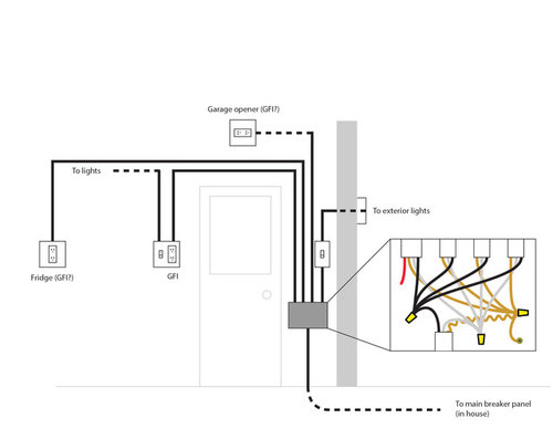
- The supply wire from the main panel has what looks to be several twisted ground wires (first diagram, pictured). I’ve never seen this before, but assume it’s an old standard that’s now dated?

- In the current wiring setup, any specific reason why 12/3 cable was used to power the 2 gang box outlet/switch? As you can see in the picture in the first diagram, the red wire is not used. Am I missing something…?

- Do either the opener or fridge need to be on separate circuits according to latest code?

- Is a single pole 15 amp circuit enough for all of these additions? Does it violate any code?

- Are GFI’s required for all outlets?


I’ve done some basic wiring, but please let me know if anything looks awry in my second diagram. Thanks for any input!


CURRENT


PLANNED


Comments (14)

  • 11 years ago

    Twisting isn't sufficient, you must use a listed connector (such as a wirenut). But otherwise that's OK.

    If you have only one circuit serving an outbuilding (even if it is a MWBC) you don't need a ground system (rods) there. The 12-3 is commonly used to provide a 20A MWBC to outbuildings. You'd have to look at your main panel, but you could get 2 20A circuits out of this.

    The code doesn't care if you put the garage door opener and refrigerator on the same circuit provided he manufacturer doesn't call for a dedicated circuit (unlikely).

    15A probably will be fine.

    All 15 and 20A 120V circuits in garages must be protected by GFCI. A GFCI (either breaker or as the first receptacle) can protect later receptacles.


  • 11 years ago
    last modified: 11 years ago

    Bonus points for nice diagrams.

    Really should have an electrician put a subpanel in the garage IMO. Then you can have various breakers and do all the wiring you desire. Hard to fully power an entire garage on one 15A circuit. Dont get me wrong, it will work but the breaker may trip when using larger power tools and you have to go in the house and keep flipping it back on. Most large power tools are going to pull more amps and require a 20A. Things like table saws and such.

    Also, you can protect a whole circuit with one GFCI using the line and load connections. Have the GFCI the first item connected then wire everything else to the load

    I am guessing they used the 12/3 from the box to the light switch because they bought the wrong wire.

  • 11 years ago

    The "twisted" is the concentric neutral in the SE type cable. Most likely, somebody has changed the original configuration of the wiring. Because of the unused red wire that is NOT feeding the building, I would guess that there was originally a multi-wire branch circuit supplying the building before a grounding conductor was required.

    Does the metal conduit go all the way back to the main panel?

    You still need a disconnect 225.31, 225.32

    If you want to turn it back into 2 circuits without a separate grounding wire going back to the main house panel, use 250.32 (B) Exception

    The ampacity of the branch circuit(s) that are necessary, depends on the ampacity of the refrigerator and door opener, in general, but I would usually treat them both as "fastened in place" 210.23 (A)

    GFCI is required for all "receptacles" not "outlets"

    The reset button on the GFCI has to be within reach without a ladder. (Door opener receptacle can be fed from another GFCI on wall)

  • 11 years ago

    Thanks for the wealth of info, guys. This is very helpful.


    I haven’t worked with GFI receptacles (I stand corrected on my terminology, thanks!) enough, but I think I’m understanding how to protect the circuit with just one of them.


    Vith, I was wondering if I’d run into any tripping issues. As of now, use of larger electrical equipment is pretty light (limited to a circular saw or a shop vac at most). However, we all know that can change, and I’d like to future proof this as best I can right now. A subpanel is clearly out of my league; I assume I’d be looking around $500, give or take a bit, for an electrician to come in and wire that up?


    Fred, thanks for the links to the detailed info. I’m not familiar with a disconnect. Is that also referred to as a “disconnect box” or “disconnect switch?” Could you point me to an image/link of a residential application? I’m finding some under these terms, but most seem to be associated with air conditioner units (perhaps the same?). Is the point of this just extra protection since the power is being served to a standalone structure?


    The metal conduit does not go all the way back to the main panel. It stops just after hitting the interior of the slab concrete basement walls. The wire then runs about 2ft to the panel.


    I’ll have to read up a bit more on 250.32 (B) Exception and 2 circuit setup. I’m not sure I quite understand my options here, or the exception/implementation.

    So, in a nutshell, it sounds like the only pressing need per code is a disconnect, correct? The system may prove to be a bit under amperage down the road, in which case I’d eventually get some help running a new 20amp circuit to the garage or even consider the subpanel.


    I’ve updated my approach and diagrams to focus on branching the circuit in the second box instead of the first since the GFI receptacle is already there... Does this look sound? Am I properly protecting the opener and fridge receptacles down the line? I don’t believe there’s any need to protect the switches, hence why they’re fed off the first pigtail – correct? There's a lot of connections here, but I think an extra deep 3 gang should be suitable. Thoughts?


    Thanks again, guys – much appreciated.


  • 11 years ago

    I have a large workshop some of which runs on GFCI protected 120V 20A circuits. I've never had a GFCI trip (though I've managed to blow the overcurrent breaker).

    Any power wiring to a building requires a disconnect at the building. That could be a circuit breaker if you have a subpanel there or as simple as a switch (but it needs to open all the ungrounded connectors). Such wouldn't cost you more than $100 in materials and the labor to install is not very significant.


    The 250.32 exception says you don't need ground rods at the building if it is only fed with a single circuit (which would include a MWBC which feeds two 120V circuits at your building because it really only counts as one).

  • 11 years ago
    last modified: 11 years ago

    What you originally had were two (HOT) current carrying wires and a concentric neutral with NO ground wire. What the 250.32(B) exception actually says is that you CAN add a grounding electrode system (usually 2 ground rods) and end up with 2 circuits with a neutral and a grounding conductor. Instead of what was done, which was turn one of the circuit wires into a neutral and use the bare wire as a ground.

    It would be better to continue the conduit so that it can be used as the grounding path instead of the neutral, or replace the old cable with a 4-wire cable. But, if it is too prohibitive to replace the conductors, you can still get two circuits WITH A GROUNDING WIRE in the garage via ground rods.

    Exception: For existing premises wiring systems only, the grounded conductor run with the supply to the building or structure shall be permitted to be connected to the building or structure disconnecting means and to the grounding electrode(s) and shall be used for grounding or bonding of equipment, structures, or frames required to be grounded or bonded where all the requirements of (1), (2), and (3) are met:

    (1) An equipment grounding conductor is not run with the supply to the building or structure.

    (2) There are no continuous metallic paths bonded to the grounding system in each building or structure involved.

    (3) Ground-fault protection of equipment has not been installed on the supply side of the feeder(s).

    Where the grounded conductor is used for grounding in accordance with the provision of this exception, the size of the grounded conductor shall not be smaller than the larger of either of the following:

    (1) That required by 220.61

    (2) That required by 250.122


  • 11 years ago

    Hmm... The grounding rod setup/installation is over my head, and maybe out of my league to tackle alone. I do have some folks I could call on who I think could understand this. Can you guys clarify though – it doesn't look like the ground rod setup is required, but Fred, you'd recommend it?

    ---

    In researching further, I'm seeing reference to 2014 NEC changes (I think 210.52(G)(1)?) that now forbids branch circuits powering garage receptacles to power anything other (i.e. lights) than those interior garage receptacles. This true?

    If so, by the book I'd have to eliminate the exterior lights from the circuit and embark on adding a dedicated one just for them, correct. This project may have become a whole lot more a PITA with that one. :/

  • 11 years ago
    last modified: 11 years ago

    Ground rod is not hard to do.

    1. Buy ground rod, fence post driver, and ground rod clamp.

    2. Drive ground rod into ground with fence post driver, then with a hammer when near the ground. (I have seen on TV a lightning mitigation contractor use a rotary hammer on hammer mode using a ground rod bit, but that is an SDS Max, I only have an SDS plus)

    3. Install ground rod clamp on ground rod

    4. Run ground wire to disconnect box.

  • 11 years ago
    last modified: 11 years ago

    I think the revisions to 210.52(G)(1) are open to interpretation. I would rather take it to mean that you can't extend the wiring from the GFCI on the side of the house to go to the garage, or use that garage circuit for landscape lighting out of the garage. I don't think it is referring to a light at the entrance to the garage.

    "embark on adding a dedicated one just for them"

    That would be the ONLY reason for the ground rod....it gets you two circuits if you attach each insulated wire to the two separate terminals of a two pole breaker at the main house panel. ;)

  • 11 years ago

    The real issue for interpretation is whether an outbuilding garage even counts as a dwelling unit subject to 210.52 at all.


  • 11 years ago

    Great points on 210.52. Does seem like what I'm trying to do doesn't genuinely interfere with the intent of that revision, but who am I to know for sure...

    OK, I believe I'm understanding the ground rod setup a bit better now. Two hots coming through, so the ground rods provide an adequate grounding from the wiring in the garage.

    So, in the current setup or as I have diagramed above still maintaining a single circuit, is this system inadequately grounded? I had assumed the circuit being fed consisted of a live, neutral and ground (the twisted bare). However, it seems I'm misinterpreting that based off your description, Ron?

    Regarding the disconnect... Fred, from your updated diagram, it looks like this just replaces the first junction box. Is this, or something like it, what you guys are referring to?

    http://www.homedepot.com/p/GE-30-Amp-240-Volt-Non-Fuse-Indoor-Safety-Switch-TGN3321CP/100674081

    Any specs I need to be aware of when choosing one? Fused vs unfused, etc?

    --

    Again, thanks for bearing with my lack of terminology and expertise. You guys have been very helpful.

  • 11 years ago

    @Ron

    "210.52(G)(1) Garages. A 15A or 20A, 125V receptacle is required in each attached garage and in each DETACHED garage with electric power....."

  • 11 years ago
    last modified: 11 years ago

    "So, in the current setup or as I have diagramed above still maintaining a single circuit, is this system inadequately grounded?"

    As a single circuit, it is presumably grounded just fine, as long as there is a proper grounding electrode system back at the main house panel.

    "I had assumed the circuit being fed consisted of a live, neutral and ground (the twisted bare). "

    As it is set up at the current time, that is correct, but it wasn't originally wired that way when the actual wire was installed. They didn't DO ground wires back then, and a "bare wire" does not infer that it is a ground wire, just not "ungrounded" (HOT). That is a cable with a concentric neutral. I doubt that either of the insulated wires are "identified" as a neutral (white insulation).

    "200.2 (A) Insulation. The grounded conductor (neutral), WHERE INSULATED, shall have insulation that is (1) suitable, other than color, for any ungrounded conductor of the same circuit on....."

    "200 .6 Means of Identifying Grounded Conductors.

    (A) Sizes 6 AWG or Smaller. An INSULATED grounded conductor (neutral) of 6 AWG or smaller shall be identified by a continuous white or gray outer finish or by three continuous white stripes on other than green insulation along its entire length. Wires that have their outer covering finished to show a white or gray color but have colored tracer...."

    "Regarding the disconnect... "

    This depends on the final decision of how you wire it. As it is wired right now, you would only need a standard toggle switch (just like the ones that turn on the lights). If you make it 2 circuits, you may only need 2 standard toggle switches, (just like I cut and pasted them out of your original drawing). You really only need something that looks more industrial if you need to install over current devices. Do you know what the actual wire gauge of the cable going from the house to the garage is? Back then, a common thing to do was to put a dryer receptacle in the garage. (Funny enough, I just noticed that there is a documentary on the outlawing of clothes lines in many parts of the country when the dryer became popular.) In other words, that may have originally been a 30 amp wire and a gas line to make provisions for either type of clothes dryer.

  • 11 years ago

    Your present garage circuit is 15 amp. That is barely enough for minimal garage lights, a door opener, and one outlet box with 2 outlets. You may need to add another circuit from the supply panel in the house or upgrade the present circuit to higher current. However, a higher current circuit requires larger wire and it may not be possible to pull new wires through the existing installation. Adding another circuit is more practical.

    A word of caution. You will likely need a building permit and have this job certified by a licensed electrician to keep your fire insurance in force. If you should have a fire and the insurance inspector finds that you had a cobbled owner installed wiring that was not certified and inspected, the insurance company company could use this to deny coverage.