Software
Houzz Logo Print
webuser_543068779

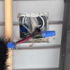
Is the wiring correct?

6 years ago


can you feed two 14/3 with one 14/2 from one 3 way switch?

It’s hard To see how they wired the rest of the garage but it appears that L2 is running power only to two lights and is not getting enough v to turn the lights on. L3 is running power to the garage opener and Two exterior lights. all the wires are behind walls And under Plywood flooring in the attic so it’s hard to tell exactly what they did with out tearing it all down and I’m not even sure about the wires running to a few outlets.

Comments (12)

  • 6 years ago

    Is there not a second three-way switch somewhere?


  • 6 years ago

    Are the blue wires supposed to be the neutral (white) ones?

  • 6 years ago

    There’s no second 3way switch and yes, those lighter lines are to represent the white wires, just trying to define them. I did not include the ground wires.

  • 6 years ago

    So you have a white wire connected to a black one?

  • 6 years ago

    Right exactly. I just Move into this house not long ago and noticed this recently. That’s how they had it.

  • 6 years ago

    That looks, uh, kind of unusual. I'd have to see what's at the other end of those cables to determine what's going on.

    It could be a totally clueless previous homeowner's DIY, or it could be a clever hack done by someone with electronics background. For example, an alternative way to use a 3-way switch is to control 2 lights when you always want one on, but never both.

  • 6 years ago

    Thank you. I was hoping that I wouldn’t have to completely follow each line because I didn’t want to have to take up all the plywood and rip down the walls. What they did for those cords don’t make sense either. Seems like a DIY type of job.

  • 6 years ago

    Mostly concerned that it’s not going to draw too many amps and possibly start an electrical fire. Is that possible?

  • 6 years ago

    Tracing out a circuit like that can be done without tearing out walls. You do have to cut the power and remove most or all of the fixtures, receptacles, and switches.

    Partly cribbed from one of my posts in an earlier thread:

    When you can't see where anything is going, you trace electrically.

    Some people recommend the Fox and Hound, an RF tracing device. I pefer an old fashioned approach.

    Since you seem to have grounded wiring, with any luck you can use the ground as a return for your testing. Read on.

    Start by drawing up a rough electrical floor plan of the area of the house you're working in. Draw on every switch, light, and receptacle.

    My preference for circuit testing is a low voltage test light. You want a relatively low current source (battery) for safety, in case you accidentally connect to a short circuit. I used to use a 6 volt screw-post lantern battery for the power source, when they were common in hardware stores. Now that those are hard to find, I have a 4-cell D-cell holder with 4' or so long clip leads attached.

    My tracer for the other end of the circuit is a flashlight bulb screwed into a miniature socket with pigtails, and alligator clips on the ends.

    You can probably buy something similar to my homemade setup, but I haven't looked.

    Power off! If you work circuit by circuit, be careful; once in a while you'll find more than one circuit in a single box, which can be an unpleasant surprise when you've opened only one breaker and think you have the power off. It's safer. if more hassle, to open the main breaker.

    Remove ALL the wiring devices in the area you're testing - switches, receptacles, light fixtures, whatever. Take MANY MANY MANY photos as you remove them, so you can put it all back together the way it was before.

    Pick a box to start at. Connect either battery clip to ground, doesn't matter which, and the other one to the wire in that box that you want to trace.

    Take your test light to the other boxes nearby. Clip one of its wires to ground. Poke the other wire around in the boxes until you find the wire that makes the light go on.

    Mark those wire ends by folding on bits of tape and writing numbers on the tape. You can use black electrical tape with a nifty specialized Sharpie that writes in silver on black, or white vinyl tape with a regular fine-tip marker.

    Now you know where THAT wire goes and what it might do.

    As you test, go to your diagram and fill in the connections between boxes (and eventually perhaps to the main panel) with lines. At some point, you'll look at your drawing and say to yourself, "I see how this works. How did I miss that before?"

  • 6 years ago

    According to your drawing, L2 doesn't have any neutral wires, if the white (indicated as blue) one is powered. You could look at that location and measure the voltage at each wire. Where would the device there get it's return current connection? Someone could have illegally used the ground.

  • 6 years ago

    Do you have any blank plates anywhere, probably near a door? Someone might have removed the other 3-way switch and put a blank plate over the box.

Sponsored
Peabody Landscape Group
Average rating: 3.5 out of 5 stars8 Reviews
Franklin County's Reliable Landscape Design & Contracting