Software
Houzz Logo Print
andrew_cursi

Wiring new lights

6 years ago

My living room does not have any existing lighting, but it does have two three way switches that control the bottom halves of two outlets. Both switches control the bottom halves of both outlets. The wire that connects the two three way switches runs straight across the room through the ceiling. I want to install two recessed lights in line with that wire and then in the middle of those two recessed lights but across several ceiling joists, I want to install a ceiling fan light fixture. So, my question is, how can I tap into the wire connecting the three way switches - going recessed light, ceiling fan, recessed light - so that both switches will control all the lights. I've attached a few pictures. Not sure if they will help. I am comfortable doing the electrical work as long as I know I am connecting the right wires together. Any help would be appreciated.


Rough wiring diagram. Yellow represents white wires. Switch 1 and switch 2 are the three way switches that control the bottom halves of the outlets. Switch 3 controls an outside light.


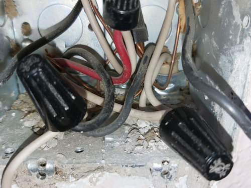
Inside junction box of switch 1 and 3


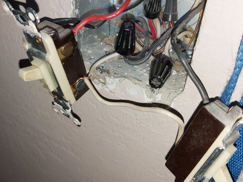
Same junction box with view of switch 1 (on left) and 3 (on right)


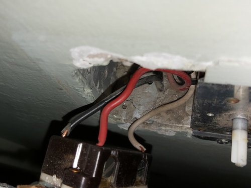
Switch 2


Comments (30)

  • 6 years ago

    What you have there violates code even if it works properly:

    1) you cannot connect white wires and black wires together unless the white wire is hot and the ends of the white wire are color coded to indicate that.

    2) you cannot put two wires under one terminal screw as with the switch on the left, and the top wire appears to be looped in the wrong direction as well.

    In addition, although I can't tell for sure because I don't know the dimensions of the box, you may already have exceeded the box fill allowance, and adding more wires would make things worse.


    I'm not trying to be a jerk, but I am not going to attempt to give you advice on how to complete the wiring project because there is already enough bad workmanship here that I don't feel confident I could anticipate everything needed to make it all code compliant and safe. If I found stuff like this in my house, I would hire an electrician to check out all of the wiring. Often when one finds sub-standard DIY work like this, it's not the only problem.

  • 6 years ago

    I see. If it makes a difference, I was not planning on adding anything to that junction box. My plan was to tap into the wire that goes up into the ceiling and add three new junction boxes for each . And I could fix the issues mentioned above. They sound like easy fixes.

  • 6 years ago

    Where are the switched outlets in your diagram? The "to outlet" looks like it's just a constant power outlet (assuming the black from the breaker box is constant power).

    Why are there a black/red/white from the breaker box? Are the black/white the supply and then the red is returning the switched power? Are the switched outlets down that way?

  • 6 years ago

    The outlets are on the same wall, down and to the right. I don't know if I can answer the other questions with certainty.

  • 6 years ago

    So the "from breaker box" was just a guess? It's not actual the cable coming from the breaker box directly? It probably is the power supply, but I'm guessing it runs through the two half-switched outlets before arriving here.

    You need to do some more detective work to see how the wires are run. Open the two outlets that are half switched and show pictures and draw diagrams of those outlets.


    In addition, you could confirm that your current "to outlet" is just a constant power outlet unrelated to anything we are concerned about. Unhook the black wire feeding that outlet from the wirenut and turn the power back on. Confirm that everything still works the way it should other than some unrelated outlets somewhere aren't working any more.

  • 6 years ago

    You're right it was mostly a guess. I based it off tracing where the power supply enters the wall from the basement. My basement ceilings are exposed so, I'm able to see where the wires are going. It goes into the wall in line with the switch. I suppose once it goes into the wall, it could have cut across to the outlets. That just seemed less likely to me. There are no wires entering the wall abeam either outlet.

  • 6 years ago

    Is the cable that you are seeing from below 14/3 or 14/2? The cable entering the switch box is 14/3 (ie. black/red/white)

  • 6 years ago

    Unless your "to outlet" is actually the power supply from the breaker box. How did you determine which cable is which?

  • 6 years ago

    You're right. It's 14/2 coming from the breaker box. So my "to outlet" and "from breaker box" should be reversed. So, is my plan to tap into the 14/3 wire that goes up into the ceiling and to the other switch even possible?

  • 6 years ago

    That makes a lot more sense. The 14/3 is taking the constant power, switched power and neutral to the half-switched outlets.

    I need to pop out for a bit, so I can't help further trouble-shoot right now. Either someone else will pop in with more advice or I'll get back to you in a bit.

    Andrew Cursi thanked greg_2015
  • 6 years ago
    last modified: 6 years ago

    You can do what you want, but the half-switched outlets will have to be changed to permanent power outlets. Switched power will not be able to come back to this box.

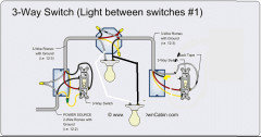
    Here's a diagram of what you are looking to do:


    Note: the black wire in the second switch box seems to be accidentally erased in the diagram above. It should continue to the common screw on the switch.

  • 6 years ago
    last modified: 6 years ago
    • So, is my plan to tap into the 14/3 wire that goes up into the ceiling and to the other switch even possible?

    No - you can't just tap into the traveler between the two switches to power the lights or fans.

  • 6 years ago

    Sounds like I'm going to need an electrician. Thanks guys.

  • 6 years ago

    The white wire should not be used for a hot line, unless it's marked at both ends.

  • 6 years ago

    No - you can't just tap into the traveler between the two switches to power the lights or fans.

    While that's correct, if you change the way things are hooked up to the switches on either end as shown in the diagram I posted above, you aren't tapping into the travellers. The travellers pass through the new light box and switched power returns to it. You use the switched power from the second box and the neutral from the first box to power the light.

  • 6 years ago

    So to do that, would I have to run new power to the switched outlets?

  • 6 years ago

    Nope. You already have 14/3 running between the switches and power coming into the first switch box. That's all you need.

    Just branch the incoming power off to the other unrelated items (ie. the switch for the outside light, the outside light, and the half-switched outlets that will now be constant power outlets) then forget about those wires and circuits.

    Then just hook everything else up as shown in the diagram and pigtail to the incoming power (black/white) wirenuts that are supplying all the other stuff.

  • 6 years ago

    Ok that makes sense. Only other question I have then is in that diagram you gave me the black wire leading to the switch on the right seems cut off. Where is it going?

  • 6 years ago

    Ok, I can do

  • 6 years ago

    I actually just noticed that too and edited the post to address it. It's just been accidentally erased and should continue to the common screw.

  • 6 years ago

    Great. Thanks a lot. You've made it pretty clear.

  • 6 years ago

    Yes - you can rewire the circuit as greg describes - you need a neutral wire for the lights. You will not be able to have switched ceiling lights and the switched outlets.

  • 6 years ago
    last modified: 6 years ago

    Then there's the other general electrical safety things that you should address as mentioned earlier.

    (1) White wires that aren't being used as neutrals should be remarked. This is minor and is often not done, but using a sharpie or a bit of electrical tape to wrap around it is a good idea.

    (2) One wire under each screw.

    (3) Wires should wrap clockwise around the screw so that as you tighten the screw, it gets pulled into the screw instead of pushed out.

    (4) Use appropriately sized wirenuts for the number of wires that you are connecting together.

    (5) Novices sometimes find it easier to pretwist wires together (clockwise) when it's more than three wires under a wirenut, but 'to pretwist or not pretwist' is a hotly contested argument on the internet. :)

    (6) Don't tape wirenuts on. Again, this is a hotly contested debate but wirenuts should never be so loose that it requires tape to keep it on. If it's that loose, you've done it wrong. And the tape just makes a sticky mess for the next guy.

  • 6 years ago

    Noted thank you. One thing I just thought of. Since there is 14/3 running to the outlet also, what does the red wire going to the outlet connect to? Or would it just be capped off?

  • 6 years ago
    last modified: 6 years ago

    The red would be powering the switched half of the receptacles. If you just capped it off, then that half won't have power.

    You have two options:

    (1) Hook the red up to the constant power source.

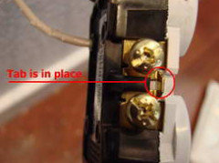
    (2) Cap the red wire. Open the half powered receptacles and disconnect the red from those outlets and cap it. Connect the constant black power to where the red was connected (as well as where it currently is). Or replace the receptacle with a new one that doesn't have the little tab broken off on the side that separates the two halves of the receptacle.

    While (1) is obviously the easiest, (2) will cause less confusion for the next person who tries to modify these circuits.

  • 6 years ago

    If you don't know what I mean by "the tab", this is what I'm talking about.


  • 6 years ago

    Ok. Option 2 doesn't seem too difficult. I'll probably go that route. Thank you very

  • 6 years ago

    Another tip.

    It looks like your current switches use the 'backstab' holes to connect the wires to them. Those are notoriously bad. While you are technically allowed to use them, they are often the cause of loose connections.

    Use the screws. They're much better and more reliable.

  • 6 years ago

    They do yes. I'll switch those around. Thanks.