Software
Houzz Logo Print
dstanton007

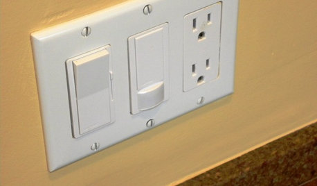
How to wire double light switch

10 years ago

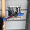
Here is a photo of the wiring. The white romex i believe is an attic fan.
http://s31.postimg.org/u2as2yzyz/IMG_3174.jpg

Whenever the black wires are hooked up the fuse pops. Only one of the black wire has power. One of them though shows 75 volts on a mutlimeter when i am testing it against the other black wire. Shouldnt I have 110 volts on every wire connecting to the live wire?

Comments (13)

  • 10 years ago

    For this purpose, voltage is not measured black wire to black wire. It's measured black (hot) lead to ground (bare) or neutral (white).

    What was there previously and how was it hooked up? One cable = incoming power; one cable = attic fan(?); third cable = leads to a switch or carries the power downstream or? How it should be connected depends on what you are connecting. Is the switch on your device for the fan or that receptacle?


  • 10 years ago

    So I believe it's:

    1) Incoming power
    2) Ceiling Light
    3) Caries power downstream
    4) Attic fan

    All the white wires except for the attic fan are all connected together. Should I connect the attic fan as well to the rest of the white wires?

    Since there is only 1 live source, when I connect all of the black wires, the breaker shouldn't pop. All of the devices should be on at the same time? What if there is a short in the attic fan?

  • 10 years ago

    How have you verified the purposes for the cables? Don't I see one black wire wire-nutted to a white? (Hard to be positive from the photo.) That is usually a switch loop related connection. Could there be a switch elsewhere for the fan or light?

    What is the switch for that you are installing?

  • 10 years ago

    There's more to wiring than just connecting all the wires of the same color together. Yours is a common issue with those wiring switch loops. You have just made the switch (when closed) connect the hot to the grounded connection which hopefully just trips the breaker.

    You need to identify the black wire going to the lamp and the black wire going back to the panel. The latter gets connected to the white wire going to the switch (and any other black wires leaving the box going elsewhere most likely) and the former gets connected to the black wire going to the switch, alone.

  • 10 years ago
    last modified: 10 years ago

    Randy and Ron,

    Sorry for the bad photo. Definitely there isnt a white wire wire nutted to a black. Lots of dirt makes the other black wire look white. Let me see if I can explain the setup in more detail.

    We have the 3 original wires from the house
    1) Live power
    2) Ceiling Light
    3) Downstream power

    All 3 white wires of the above are wire nutted together.
    Only two of the black wires are wired together. My guess is that this is the live power and the downstream power wires.

    So we have one black wire with live power, one black wire for the light, and lastly the new romex(black and white) which is for the ceiling fan. I know it's for the ceiling fan as this house is 40 years old, and the fan was added when it was re-roofed 10 years ago.

    Should I connect all 4 white neutral wires together?

    What I would like to achieve is have the dual light switch be able to turn on the light, and turn on the ceiling fan separately.

    Thanks

  • 10 years ago

    Hi Randy and Ron,

    Hoping for more input, any thoughts?

  • 10 years ago

    If the configuration is as you guess (a term which calls for extra caution) the black wires that are connected would be connected to the LINE side of the dual switch (that's the side that has a jumper connection between the two screws). The black wires from the light and the fan would each go to a terminal on the LOAD side of the dual switch. All four white wires are connected and all four ground wires are connected to each other, the box and the ground terminal on the switch.

    Did you use an ohmmeter to see if there was a short that was causing the fuse to pop? Do so with the power off and before the switch is installed. Each black to ground and to neutral. Zero ohms indicates a problem.

    Another issue; that junction box is not adequate for the 8 conductors, grounding wire and switch that you are planning to stuff in there. I'm a little rusty on it, but I believe you need a minimum of 22 cubic inches.


  • 10 years ago

    Hi Greg,

    It was a double switch before. The plastic portion of
    the switch "handle?/flipper?" broke on the light switch. My
    father in law attempted to swap it himself, he called me when it didn't
    work. When I showed up the ground was hooked up to a normal terminal and
    not the ground terminal. I've been trying to figure it out without luck
    so far.

    Thanks,

  • 10 years ago

    Hi Randy,

    Ok, that's how I thought it should be setup. I'll check for shorts now. Can you elaborrate on how I should test? Not sure what you mean by each black to ground and do a neutral. I have a fluke multimeter I can use.

    Thanks,

  • 10 years ago

    If the ground was connected to a 'normal' terminal, you probably found the reason for the fuse failure and don't need to do the ohmmeter test after correcting it.

    If you do test, one probe goes to the black lead, the other to the white. Then move the second probe to the ground. Repeat for the other cables.

  • 10 years ago
    last modified: 10 years ago

    So you FIL just pulled stuff apart and forgot how it went back together? Great!

    Did he touch any of the wirenuts? If not, that simplifies things. That means you don't have to touch them.

    If there are only 4 wires (ignoring the ground) that need a place on the new switch then from that picture you posted, I'd say that the cable with the black/white is a switch loop and should be connected to one of the switches and the other two blacks are the feed and load side for the other switch.

  • 10 years ago

    Step 1

    Turn off the breaker that supplies power to the circuit. A test on the circuit will verify you turned off the right breaker. Touch one lead from the two-lead tester to the black wire inside the switch box leading back to the circuit panel. The tester will not light if you turned off the right breaker. There are two other black wires inside the switch box that lead to each light fixture; these will not have power running through them until connected to the switch

    Step 2

    Tie the three white wires together inside the switch box, two white wires connected to the two separate lights and the white wire from the circuit panel. Twist one red wire connector clockwise onto all three white wires to tie them together. Push this set of wires to the back of the switch box.

    Step 3

    Connect the three bare copper ground wires together from inside the switch box, the two bare copper wires that lead to the two separate lights and the bare copper wire that leads back to the circuit panel. Use an additional red wire connector on all three wires, connecting them. Push the set of bare copper wires into the switch box next to the set of white wires.Step 4

    Wrap the black wire from the circuit panel around the brass screw on the right side of the double switch. Tighten the screw to hold the wire. The circuit panel black wire supplies electricity to the double switch.

    Step 5

    Wrap one black wire from one of the light fixtures around one of the brass screws on the left side of the double switch. Wrap the remaining light fixture wire around the remaining screw on the side of the double switch. Tighten both brass screws to hold the black wires from the light fixtures to the double switch.

    Step 6

    Install the double switch inside the switch box. Push the switch and its wires into the box, connecting the switch to the box at the top and bottom using the screws that came with the double switch. Cover the switch with a duplex cover plate and turn on the breaker to the circuit.