Software
Houzz Logo Print
chachi69

Need solution for an inline dimmer.

10 years ago
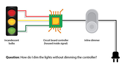
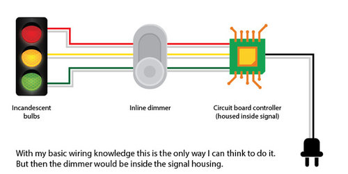
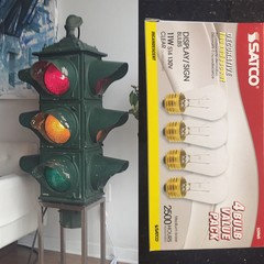
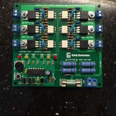
I have an antique traffic signal using incandescent bulbs for which I purchased a circuit board controller that will make it cycle through G-Y-R as it when it was still in service. I'm using 20W bulbs but I'd still like the option to dim them lower at times. The problem is that the controller can't operate with less than 90V so the dimmer has to somehow bypass the controller. If I put the dimmer inside the signal that would work, but I don't want to open the signal every time I want to adjust the overall brightness.

Comments (17)

  • 10 years ago

    A remote controlled dimmer. Great idea and one I had not considered. I'll see if those exist. Thanks for the comment.

  • 10 years ago

    I just had the excellent and very expensive idea to use white LIFX LED bulbs in the signal. That way the signal is always 'on' and I control the lights, including brightness, entirely with the LIFX smartphone app. I didn't feel like illustrating it but the signal is actually an old Crouse-Hinds 4-way, so 12 bulbs total. That would require $480 in LIFX bulbs. Yikes!

    http://www.lifx.com/products/white-800?variant=933783339

  • 10 years ago

    Lutron makes remote dimmers, they are under $100 for sure. If you want a smartphone app controlled dimmer switch there are any number of solutions for that as well - Lutron Caseta, z-wave, etc.

    chachi69 thanked freeoscar
  • 10 years ago

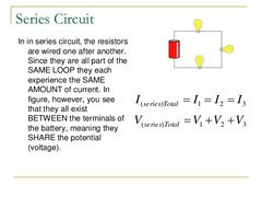
    In a series circuit, voltage is additive no matter what order you put the resistance.

    .

    chachi69 thanked User
  • 10 years ago

    Fred, I'll admit total ignorance on how the traffic light circuit board works. Are you stating that it's wired in series with the lights?

    If that's the case, would that mean that if one of the bulbs burned out then the circuit board would stop working altogether?

    For example (and for simplicity's sake, lets pretend that each colour signal only has one bulb):

    If the red bulb burned out, that would break the circuit when the board switched to that light, so it wouldn't be able to switch back to the yellow or green lights.


    I would have assumed that the circuit board was run in parallel so that it would still continue working.

    chachi69 thanked greg_2015
  • 10 years ago

    The traffic light circuit board is just a high tech switchboard. For each light, there is a switch (12). The switchboard just turns one off when it turns the other on....

    Switches are always in series with lights. The switchboard has 12 individual switches in parallel with respect to the other switches, but in series with the light it controls.

    Dimmers are like switches. They are run in series with the light they control. It doesn't matter whether you put the dimmer before or after the switchboard, it is still in series with each light and switch inside the switchboard that corresponds to each light.

    chachi69 thanked User
  • 10 years ago

    But aren't some switches in both series AND parallel?

    I'm thinking of the timer in my bathroom. It's a switch. If I remove the light bulb or the fan or whatever from the circuit, the little indicator on the timer still works and it still counts down and turns itself off. If it was a purely series situation, then the circuitry wouldn't work at all without the downstream load. Right? That's why the timer requires the neutral wire as well. If it was purely series, it would only need the hot.

    Would the switchboard not work the same way? It requires the full voltage from the feed to work it's internal stuff so putting the dimmer before the board would screw up the parallel components. Putting the dimmer after the board would only affect the series aspect.

    BTW - I'm not trying to argue with you. I'm asking honest questions.

    chachi69 thanked greg_2015
  • 10 years ago

    Thanks Fred S. "It doesn't matter whether you put the dimmer before or after the switchboard, it is still in series with each light and switch inside the switchboard that corresponds to each light."

    I'm still not entirely clear on why it doesn't matter, because the circuit board "switch" needs a certain amount of power (≥90v) to perform whatever functions it does to know when to switch the lights off/on, or so I was told by the vendor I purchased it from.

    Does it matter whether I use the type of dimmer that reduces the voltage across the series vs. the type that interrupts the voltage up to 120 times per second to achieve dimness?

  • 10 years ago
    last modified: 10 years ago

    "That's why the timer requires the neutral wire as well."

    Correct. The timer is in parallel. The timer turns off the switch which is in series. The timer turns off the switch via a relay.

    "Would the switchboard not work the same way?"

    Not sure. It depends on how the switchboard is wired.

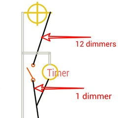
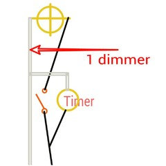
    If the "timer" is in parallel with relays, then there should be a way to insert one dimmer after the circuit splits off for the timer, but before the switches. (In theory) instead of 12 dimmers.

    Many old "timers" and indicator lights ran a small amount of electricity through the bulb instead of needing a separate neutral. You couldn't tell that there was still electricity running through the bulb when the light was off because the current was too small to make the filament glow. (this is the situation I am thinking about) Circuit boards are often run more in a series configuration, or combination series parallel that is hard to separate for the purpose of adding a dimmer.

    "I'm still not entirely clear on why it doesn't matter, because the circuit board "switch" needs a certain amount of power (≥90v) to perform whatever functions it does to know when to switch the lights off/on"

    It does matter, you just might end up with the same problem either way. These are the same as far as voltage across any light/resistor/dimmer/circuit board, etc.

    "Does it matter whether I use the type of dimmer that reduces the voltage across the series vs. the type that interrupts the voltage up to 120 times per second to achieve dimness?"

    I don't know for sure, but my guess is that you would have other problems with the same outcome of failure. (The faster cycle may speed up the timer proportionally) Unless the control circuits on the board are truely in parallel with the actual switches.... hard to say. If the control parts of the circuit board are in parallel, then any dimmer should work on the load side of the circuit board like you were thinking.

  • 10 years ago
    last modified: 10 years ago

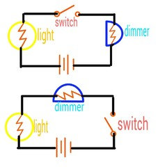
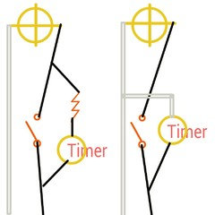
    To clarify, If the controller is configured like the one on the left, it probably won't work with a dimmer.

    If the controller is configured like the one on the right, a dimmer should work in either location.

    If you can group/ bundle the neutrals for the lights at this location, you may be able to do one dimmer. (Not a dimmer that [normally] requires a neutral)

    But, I don't really know how the controller is wired. Is there any online schematics for this controller?

    chachi69 thanked User
  • 10 years ago

    Fred S, these are the tech specs:

    SPECIFICATIONS:

    • Supply Voltage: 90VAC to 125VAC
    • Output Rating: 120VAC @ 4.6A per channel (fused at 10A)
    • Input Connector: 14-26AWG, 250VAC @ 16A
    • Output Connector: 16-26AWG, 125VAC @ 10A
    • Delay Range: VR1: 20-130 seconds (yellow 4 to 7 seconds via jumpers)
    • Board Dimensions: 3.94 x 3.94" (10 cm x 10 cm)
    • Board Material: 0.062" (1.6 mm) FR-4, with green solder mask and top layer silk screen
    • Finished Weight: 2.7 ounces (76 grams)

    http://www.ebay.com/itm/261651892087

  • 10 years ago

    Do you have the instruction sheet and scematics? I can't find what I am looking for online. A picture of the wiring diagram and schematics might help.

    I have a feeling that I might need a unit in hand (and a meter) to fully understand how the circuits work if the wiring diagram isn't clear enough :-/

  • 10 years ago

    I don't think I need the schematics. What you have is a controller chip (lower left) tand then SIX units which appear to be opto-isolators feeding a triac.

    I'm going to have to say that even if you were able to cut the traces on the board and modify it to put a common dimmer in, it's going to be difficult to get it to work given the nature of the circuit (it may be hard to get the TRIACs to fire properly if you feed them with a very reduced waveform as from another TRIAC/SCR dimmer). I suggest you just put three individual dimmers on the outputs. That's going to be a lot easier.

    I used to spend long hours fixing theatre and disco lighting systems in my youth. This unit looks cheesier than most.

    chachi69 thanked Ron Natalie
  • 10 years ago

    Thanks to everyone in the HOUZZ community for all the comments. I took the low road and purchased twelve 11W display/sign bulbs. I don't want the signal any brighter than that in the house. It's not like I'm really trying to direct traffic, after all.

  • 10 years ago

    Great. Do you actually have all six channels wired up (I was envisioning your signal head only having three lamps but yours seems to have ones for each direction).

    chachi69 thanked Ron Natalie
  • 10 years ago
    Yes, 12 lights in all for six channels. The output is basic two phase traffic control.
Sponsored
Wannemacher Interiors
Average rating: 5 out of 5 stars26 Reviews
Customized Award-Winning Interior Design Solutions in Franklin Cnty OH