


Tecumseh voltage regulator problem
baymee
12 years ago
Sort by:Oldest
Comments (16)
Related Stories

LIGHTINGThe Lowdown on High-Efficiency LED Lighting
Learn about LED tapes, ropes, pucks and more to create a flexible and energy-efficient lighting design that looks great
Full Story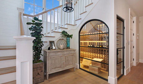
LIGHTINGWhat to Know About Switching to LED Lightbulbs
If you’ve been thinking about changing over to LEDs but aren't sure how to do it and which to buy, this story is for you
Full Story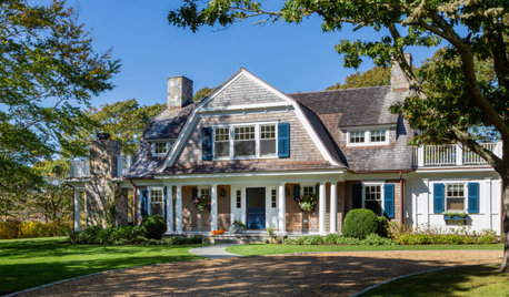
CONTRACTOR TIPSYour Complete Guide to Building Permits
Learn about permit requirements, the submittal process, final inspection and more
Full Story
LIGHTING5 Questions to Ask for the Best Room Lighting
Get your overhead, task and accent lighting right for decorative beauty, less eyestrain and a focus exactly where you want
Full Story
WINDOWSHow to Ditch the Drapes and Let Your Windows Shine
If your home has beautiful windows and you don’t need to hide a view, consider dressing them in these elegant, creative ways
Full Story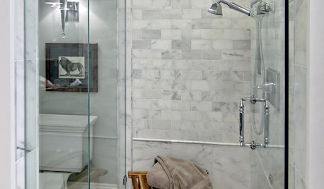
BATHROOM DESIGNHow to Settle on a Shower Bench
We help a Houzz user ask all the right questions for designing a stylish, practical and safe shower bench
Full Story
KITCHEN DESIGN7 Awesome Add-ons for Kitchen Cabinets
Useful gadgets, docks for your devices, extra lighting ... when it comes to cabinets, do look down
Full Story
GREEN BUILDINGThe Big Freeze: Inventors Break New Ground to Keep Things Cool
Old-fashioned fridges can be energy guzzlers, but there are more eco-friendly ways of keeping food fresh, as these global innovations show
Full Story
HOUZZ TOURSWorld of Design: 9 Energy-Smart Australian Homes
With their innovative features and diverse surroundings, these 9 award-winning homes have struck gold on the Aussie design stage
Full Story
exmar zone 7, SE Ohio
tomplum
Related Professionals
Vernon Hills Landscape Architects & Landscape Designers · Paradise Landscape Architects & Landscape Designers · Washington Landscape Architects & Landscape Designers · Edmond Landscape Contractors · Annandale Landscape Contractors · Canby Landscape Contractors · Downey Landscape Contractors · Golden Gate Landscape Contractors · Lynn Landscape Contractors · Pikesville Landscape Contractors · Wayland Landscape Contractors · Doctor Phillips Window Contractors · Cicero Window Contractors · Revere Window Contractors · South Laurel Window Contractorsmownie
baymeeOriginal Author
baymeeOriginal Author
ericwi
mownie
baymeeOriginal Author
ericwi
mownie
mownie
baymeeOriginal Author
baymeeOriginal Author
tomplum
baymeeOriginal Author
baymeeOriginal Author